ZHAO Fuqi, XU Peibao, WEN Heming. Influence of Specimen Size in SHPB Tests on Concrete[J]. Chinese Journal of High Pressure Physics, 2018, 32(1): 014101. doi: 10.11858/gywlxb.20170532
Citation:
ZHANG Ruike, GUO Rui’ang, XIAO Xiong, HE Duanwei. Measurement of the Melting Point of Hexagonal Boron Nitride under Pressures below 5 GPa[J]. Chinese Journal of High Pressure Physics, 2024, 38(6): 063401. doi: 10.11858/gywlxb.20240813
In this study, a flash-heating device was designed and assembled to achieve instantaneous discharge heating of samples under high pressure in the DS 6×14 MN domestic hinged six-anvil large chamber press. By combining large chamber static high pressure and instantaneous discharge heating technologies, the melting state of crystals has been determined by the nucleation and growth characteristics during solidification. The melting behavior of h-BN powder crystal under high pressure was studied by instantaneous discharge heating treatment. Using scanning electron microscopy (SEM), the microstructures of samples obtained by high-pressure instantaneous discharge heating treatment was analyzed in order to assess the melting state of h-BN crystals. It was determined that the melting points of h-BN under 3.4 and 4.3 GPa are (4251±150) K and (4531±200) K, respectively. These results are beneficial for exploring the applications of h-BN and revising the existed temperature-pressure phase diagram of boron nitride.
Dynamic compressive strengths of concrete-like materials are usually obtained by conducting laboratory tests such as split Hopkinson pressure bar (SHPB) tests[1-5].Many empirical formulae for dynamic increase factor (DIF) based on laboratory test data were reported in the related literature Ref.[6-9].
It has to be mentioned here that the SHPB test data available for concrete materials in the literature were very scattered[7-10] due to the combined effects of strain rate, inertia and specimen size.More comprehensive investigation and discussion of the possible influencing factors can be also obtained in Ref.[1, 2, 7-11].The inertia (confinement) effect has been widely investigated experimentally[12], theoretically[13-14], numerically[5, 15] and an empirical equation for the dynamic increase factor due to inertia (confinement) effect was suggested in Ref.[16], which took no account of the effect of concrete specimen size.As strain rate effects on the compressive strengths of concrete-like materials play an important part in the construction of material constitutive models which, in turn, exert a great deal of influence on the numerical simulations of concrete structures subjected to intense dynamic loadings, it is, therefore necessary to obtain the pure strain rate effect data by eliminating the data due to the effects of inertia (confinement) and specimen size from SHPB tests.
In the present study, numerical simulations with a rate-independent material model are carried out on the influence of specimen size in SHPB tests on concrete and a new empirical equation for the dynamic increase factors due to inertia (confinement) effect is proposed which takes account of specimen size effect through its volume.Comparisons are made between the results from the numerical simulation and those from the new empirical formula and discussed.
1.
Material Model
The computational constitutive model for concrete developed in Ref.[1] is used to simulate the SHPB tests on concrete in the present study.This material model consists of equation of state (EOS), strength model including Lode effect, damage criteria and strain rate effects, etc.
1.1
Equation of State
The porous equation of state is used in the present study and can be expressed as[17]
ˉμ=ραρ0α0−1=αα0(1+μ)−1
(1)
where μ=ρ/ρ0-1 is the volumetric strain, in which ρ and ρ0 are respectively the current and initial densities; α=ρs/ρ and α0=ρs0/ρ0 are the current and initial porosities in which ρs and ρs0 are the current and initial densities of solid (fully-compacted) material.
For μ > 0, concrete material is under compression condition
where K1, K2 and K3 are the bulk moduli for fully compacted concrete material, pcrush is the pressure at which pore collapse occurs, plock is the pressure beyond which concrete material is fully compacted, n is the compaction exponent.
For μ < 0, concrete material is under tension condition.Hence, the pressure is
p=K1ˉμ
(3)
1.2
Strength Model
The strength surface of concrete can be written in the following form[1]
where fcc=fc'δm_tηc and ftt=ftδtηt in which fc' and ft are the static compressive and tensile strength, δm_t and δt[2] are the dynamic increase factors due to strain rate effects only in compression and tension, ηc and ηt[18-20] are shape functions which represent shear damage and tensile softening of concrete respectively; B and N are empirical constants; r(θ, e)[21] is the Lode effect with θ and e being the Lode angle, the ratio of the tensile meridian to the compression meridian, respectively.
By setting ftt=0 and fcc=fc'r (residual strength), the residual strength surface for concrete can be obtained from Eq.(4)
Other information about shear, tensile damage, Lode effect and strain rate effect can be found in Ref.[1-2].
2.
Specimen Size Effect
In this section, the commercial software LS-DYNA3D with user-defined subroutines is used to carry out the numerical study on the influence of specimen size in SHPB tests on concrete using a recently developed constitutive model for concrete[1] by setting the material DIF (δ) equal to 1.The inertia effect dynamic enhancement factor (Rc) can be obtained by dividing the strength results of simulation by quasi-static strength.The values of various parameters used in the material model are listed in Table 1[1].In this case, the numerically obtained strength increment of the studied specimen is attributed to the inertia (confinement) effect only.
An SHPB system contains incident and transmitter pressure bars with a short specimen between them, as shown in Fig. 1.A stress pulse of trapezium shape is applied to the incident pressure bar as shown schematically in Fig. 2 in which the incident stress starts from 0, quickly rises to the peak value of ppeak at t1, keeps as a constant for t2, then drops back to 0 after t3 and are summarized in Table 2.
Friction is an important factor which needs to be considered.However, in SHPB tests on concrete the effect of friction is negligibly small[22] in terms of its contribution to the total dynamic increase factor and is usually ignored in numerical simulations[23].Moreover, in SHPB tests measures are usually taken (i.e. by applying lubricant to both ends of concrete samples) to further reduce the effect of friction.Hence, in the present study the effect of friction is also ignored in the numerical simulations.
In this study, the dynamic strength increase factor is employed to reflect the effect of specimen size in SHPB tests on concrete.If there is no size effect there will be no difference for concrete samples with different sizes or volumes in terms of the dynamic increase factors at the same strain rate.Otherwise there will be size effect in SHPB tests on concrete.
Fig. 3 shows the numerical results for the dynamic increase factor due to inertia (confinement) effect Rc for concrete specimens with the same volume of different length/diameter ratios (i.e., Ø51 mm×51 mm, Ø64 mm×32 mm, Ø74 mm×24 mm) whilst Fig. 4 shows the numerical results for concrete samples with different volume of the same length/diameter ratios (i.e., Ø64 mm×32 mm, Ø80 mm×40 mm).It can be seen from Fig. 3 that the inertia effect is mainly related to the specimen volume and is insensitive to the length/diameter ratio when the volume and the material parameters of the specimens are kept the same.It also can be seen from Fig. 4 that the dynamic increase factor due to inertia (confinement) effect increases with the increase of the concrete specimen volume, which indicates that size effect does exist in SHPB tests on concrete as described above.
Figure
3.
Comparison of Eq.(6) with numerical results fordynamic increase factor due to inertia (confinement)effect for concrete specimens with the same volumeof different length/diameter ratios
Figure
4.
Comparison of Eq.(6) with numerical results fordynamic increase factor due to inertia (confinement)effect for concrete specimens with different volumeof the same length/diameter ratio
On the basis of the numerical results discussed in the previous section, a new empirical equation which takes consideration of the specimen size effect in SHPB tests on concrete is suggested here to describe the dynamic increase factor due to inertia (confinement) effect Rc by using the monotonically increasing and continuous properties of exponential functions in a simple and easy to use form, namely
Rc=Slg(˙ε˙ε0)+1βlg(VV0)−W+1
(6)
where S, W, β are the constants to be determined numerically, $ {\dot \varepsilon } $ is the strain rate, $ {{{\dot \varepsilon }_0}} $ is the reference strain rate for a reference specimen usually taken to be $ {{{\dot \varepsilon }_0}} $=1.0 s-1, V is the volume of a concrete specimen under investigation, V0 is the volume of a concrete sample with a reference size, say, Ø51 mm×51 mm.Set V=V0 in Eq.(6), one obtains the dynamic increase factor due to inertia effect for the reference concrete specimen Rc0.
In the following, first, one determines the values of S and W in Eq.(6) using the numerical results for the concrete specimen with the same volume (i.e. V=V0) as presented in Fig. 3 and, then, the value of β in Eq.(6) using the numerical results for the concrete samples with different sizes/volumes as given in Fig. 4.
Fig. 3 shows the comparison between the numerical results and Eq.(6) with S=6, W=2.8 and V=V0 as indicated by the dashed line.It can be seen from Fig. 3 that reasonable agreement is obtained.Further examination reveals that the value of S in Eq.(6) should not be a constant but a function of strain rate.The slope of the curve is too small at the low strain rate, and too large at the high strain rate.By using the centrosymmetric properties of the hyperbolic tangent and the x-axis paralleled, S is taken as the following form to increase the slope of the curve at the low strain rate and decrease the slope at the high strain rate, namely
S=−Fitanh[lg(˙ε˙ε0−Wi)Si]+Gi
(7)
where Fi, Wi, Si, Gi are the constants determined using the numerical results for concrete samples with constant volume as presented in Fig. 3, namely, Fi=6.0, Wi=2.8, Si=0.8, Gi=8.5.The solid line in Fig. 3 is predicted from Eq.(6) with V=V0 together with Eq.(7).It is clear from Fig. 3 that good agreement is obtained.
Fig. 4 shows the comparison between Eq.(6) with β=2.7 and the numerical results obtained for the concrete samples with different sizes/volumes.The values of all the other parameters in Eq.(6) are listed in Table 3.It is evident from Fig. 4 that the present model agrees well with the numerical simulations.
Table
3.
Values of various parameters in Eq.(6) and Eq.(7)
In order to verify the validity of Eq.(6) more numerical simulations are performed on concrete specimens with different sizes. The numerical results are also presented in Fig. 4 and comparisons are also made between Eq.(6) and the numerical results.It can be seen from Fig. 4 that good agreement is obtained.
Fig. 5 shows the normalization of all the numerical results for concrete specimens with different sizes as given in Fig. 3 and Fig. 4 with respect to those for the reference concrete sample, namely, Ø51 mm×51 mm.It is clear from Fig. 5 that all the numerical results collapse into one line.It lends further support to the validity of Eq.(6) for the dynamic increase factor due to inertia (confinement) effect which takes into consideration the influence of specimen size.
Figure
5.
Variation of normalized numericallyobtained dynamic increase factor due to inertia(confinement) effect with strain rate
The influence of specimen size in SHPB tests on concrete has been investigated numerically using a rate-independent material model.A new empirical equation for the dynamic increase factor due to inertia (confinement) effect has also been proposed which takes into account the specimen size effect through its volume.It is demonstrated that the new empirical formula agrees well with the numerical results for SHPB tests on concrete with different specimen sizes.
SONG Z Y, WANG W, CAI G X, et al. Investigation of optical spectrum properties of hexagonal boron nitride from metal to dielectric transition [J]. Plasmonics, 2018, 13(2): 563–566. doi: 10.1007/s11468-017-0544-y
[2]
ZHOU W Y, ZUO J, ZHANG X Q, et al. Thermal, electrical, and mechanical properties of hexagonal boron nitride: reinforced epoxy composites [J]. Journal of Composite Materials, 2014, 48(20): 2517–2526. doi: 10.1177/0021998313499953
[3]
PEREVISLOV S N. Structure, properties, and applications of graphite-like hexagonal boron nitride [J]. Refractories and Industrial Ceramics, 2019, 60(3): 291–295. doi: 10.1007/s11148-019-00355-5
[4]
KIM T Y, SONG E H, KANG B H, et al. Hydrolyzed hexagonal boron nitride/polymer nanocomposites for transparent gas barrier film [J]. Nanotechnology, 2017, 28(12): 12LT01. doi: 10.1088/1361-6528/aa5f2e
[5]
TURKOGLU M, SAHIN I, SAN T. Evaluation of hexagonal boron nitride as a new tablet lubricant [J]. Pharmaceutical Development and Technology, 2005, 10(3): 381–388. doi: 10.1081/PDT-65684
[6]
DECKER R, WANG Y, BRAR V W, et al. Local electronic properties of graphene on a BN substrate via scanning tunneling microscopy [J]. Nano Letters, 2011, 11(6): 2291–2295. doi: 10.1021/nl2005115
[7]
REVABHAI P M, SINGHAL R K, BASU H, et al. Progress on boron nitride nanostructure materials: properties, synthesis and applications in hydrogen storage and analytical chemistry [J]. Journal of Nanostructure in Chemistry, 2023, 13(1): 1–41. doi: 10.1007/s40097-022-00490-5
[8]
SHTANSKY D V, FIRESTEIN K L, GOLBERG D V. Fabrication and application of BN nanoparticles, nanosheets and their nanohybrids [J]. Nanoscale, 2018, 10(37): 17477–17493. doi: 10.1039/C8NR05027A
WANG Y Z, ZHANG W X, SUN C H, et al. The development of the applications and synthesis of boron nitride materials [J]. Journal of Ceramics, 2018, 39(6): 661–671. doi: 10.13957/j.cnki.tcxb.2018.06.002
[10]
WANG P, HE D W, WANG L P, et al. Diamond-cBN alloy: a universal cutting material [J]. Applied Physics Letters, 2015, 107(10): 101901. doi: 10.1063/1.4929728
[11]
WATANABE T, SATAKA R, YAMAMOTO K. Effect of bias application on c-BN synthesis by induction thermal plasmas under atmospheric pressure [J]. Thin Solid Films, 2008, 516(13): 4462–4467. doi: 10.1016/j.tsf.2007.10.018
[12]
WENTORF JR R H. Cubic form of boron nitride [J]. The Journal of Chemical Physics, 1957, 26(4): 956. doi: 10.1063/1.1745964
[13]
BUNDY F P, WENTORF JR R H. Direct transformation of hexagonal boron nitride to denser forms [J]. The Journal of Chemical Physics, 1963, 38(5): 1144–1149. doi: 10.1063/1.1733815
[14]
SOLOZHENKO V L, TURKEVICH V Z, HOLZAPFEL W B. Refined phase diagram of boron nitride [J]. The Journal of Physical Chemistry B, 1999, 103(15): 2903–2905. doi: 10.1021/jp984682c
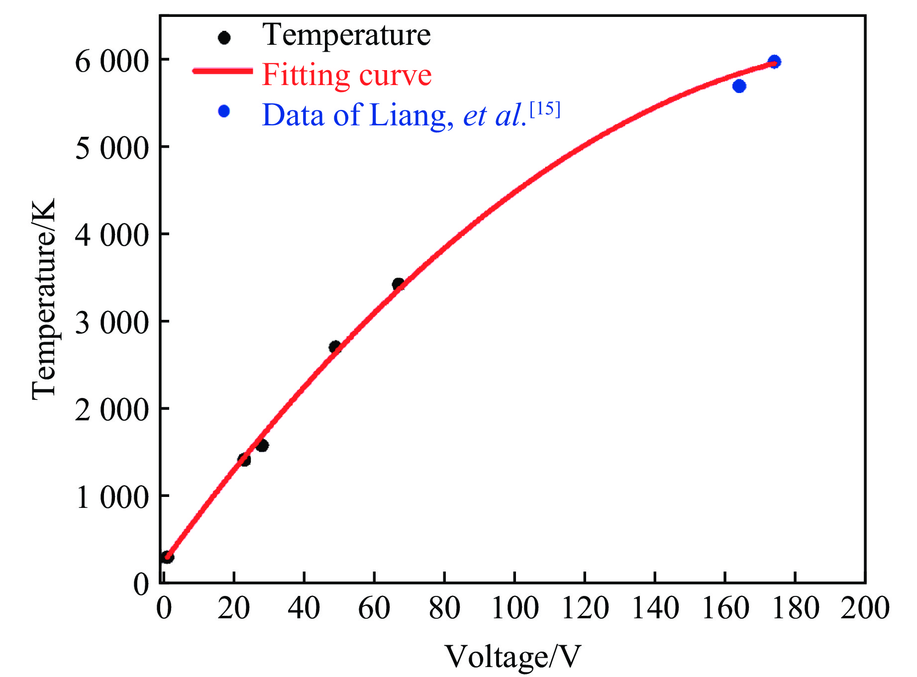
[15]
LIANG A K, LIU Y J, SHI L T, et al. Melting temperature of diamond and cubic boron nitride at 15 gigapascals [J]. Physical Review Research, 2019, 1(3): 033090. doi: 10.1103/PhysRevResearch.1.033090
[16]
ZHANG J W, LIU F M, LI S Q, et al. Recrystallization behaviour of cubic boron nitride under high pressure [J]. Journal of the European Ceramic Society, 2021, 41(16): 132–138. doi: 10.1016/j.jeurceramsoc.2021.09.036
[17]
HRUBIAK R, MENG Y, SHEN G Y. Microstructures define melting of molybdenum at high pressures [J]. Nature Communications, 2017, 8(1): 14562. doi: 10.1038/ncomms14562
[18]
WU H Y, ZHUANG X L, NIE Y, et al. Effect of heat treatment on mechanical property and microstructure of a powder metallurgy nickel-based superalloy [J]. Materials Science and Engineering: A, 2019, 754: 29–37. doi: 10.1016/j.msea.2019.03.064
[19]
IKESUE A, AUNG Y L, YODA T, et al. Fabrication and laser performance of polycrystal and single crystal Nd: YAG by advanced ceramic processing [J]. Optical Materials, 2007, 29(10): 1289–1294. doi: 10.1016/j.optmat.2005.12.013
[20]
ZHOU X F, MA D J, WANG L F, et al. Large-volume cubic press produces high temperatures above 4 000 Kelvin for study of the refractory materials at pressures [J]. Review of Scientific Instruments, 2020, 91(1): 015118. doi: 10.1063/1.5128190
[21]
BOEHLER R, ROSS M, BOERCKER D B. High-pressure melting curves of alkali halides [J]. Physical Review B, 1996, 53(2): 556–563. doi: 10.1103/PhysRevB.53.556
[22]
SHEN G Y, LAZOR P. Measurement of melting temperatures of some minerals under lower mantle pressures [J]. Journal of Geophysical Research: Solid Earth, 1995, 100(B9): 17699–17713. doi: 10.1029/95JB01864
[23]
BOEHLER R, ROSS M, BOERCKER D B. Melting of LiF and NaCl to 1 Mbar: systematics of ionic solids at extreme conditions [J]. Physical Review Letters, 1997, 78(24): 4589–4592. doi: 10.1103/PhysRevLett.78.4589
[24]
KIMURA T, OHFUJI H, NISHI M, et al. Melting temperatures of MgO under high pressure by micro-texture analysis [J]. Nature Communications, 2017, 8(1): 15735. doi: 10.1038/ncomms15735
ZHAO Fuqi, XU Peibao, WEN Heming. Influence of Specimen Size in SHPB Tests on Concrete[J]. Chinese Journal of High Pressure Physics, 2018, 32(1): 014101. doi: 10.11858/gywlxb.20170532
Figure 1. Schematic diagrams of the internal circuit (a) and connection assembly (b) of the flash-heating device (The capacitors are arranged in parallel by using 10 AWG thick wires and divided into upper-level and lower-level. The maximum output voltage is 1 kV. Simultaneous charging and discharging are not permissible.)
Figure 2. SEM images of NaCl samples after flash-heating with different voltages under (3.4±0.2) GPa (The red circled areas indicate the locations where fine grains are observed, with a distinct grain refining at 300 V. Multiple experiments are conducted, sequentially reducing the voltage to 70, 35, and 30 V, all of which resulted in the appearance of fine grains, demonstrating that at such voltages, the temperature is above the melting point of NaCl. When the voltage reduced to 25 V, no fine-grained areas can be identified in the SEM image; instead, only fragmented grains due to pressure are observed. This suggests that the melting voltage of NaCl under 3.4 GPa is between 25 and 30 V, approximately (27.5±2.5) V. At this pressure, the melting point of NaCl is 1582 K, suggesting that a voltage of 27.5 V induces an instantaneous temperature of approximately 1582 K in the sample chamber.)
Figure 3. SEM images of KCl samples after flash-heating under 3.4 GPa (No grain refinement was observed at 21 V, but appeared at 25 V within the red-circled areas. It indicates that the melting voltage of KCl under 3.4 GPa is between 21 and 25 V, approximately (23±2) V. At this pressure, the melting point of KCl is 1416 K, suggesting that a voltage of 23 V induces an instantaneous temperature of approximately 1416 K in the sample chamber.)
Figure 4. SEM images of Al2O3 samples after flash-heating under 3.4 GPa (No grain refinement was observed at 46 V, but appeared at 51 V within the red-circled areas. It indicates that the melting voltage of Al2O3 under 3.4 GPa is between 46 and 51 V, approximately (48.5±2.5) V. At this pressure, the melting point of Al2O3 is 2701 K, suggesting that a voltage of 48.5 V induces an instantaneous temperature of approximately 2701 K in the sample chamber.)
Figure 5. SEM images of MgO samples after flash-heating under 3.4 GPa (No grain refinement was observed at 65 V, but appeared at 70 V within the red-circled areas. It indicates that the melting voltage of MgO under 3.4 GPa is between 65 and 70 V, approximately (67.5±2.5) V. At this pressure, the melting point of MgO is 3419 K, suggesting that a voltage of 67.5 V induces an instantaneous temperature of approximately 3419 K in the sample chamber.)
Figure 6. Flash-heating voltage vs. temperature relationship for the flash-heating device (Black dots represent the temperature calibration points by four standard materials, and blue dots are experimental data from Liang, et al.[15])
Figure 7. SEM images of h-BN samples after flash-heating at different voltages under 3.4 GPa (The red circled areas indicate the locations where fine grains are observed, with a distinct grain refining at 300 V. Grain refinement is still observable at 96 V, but cannot be observed at 90 V. It indicates that the melting voltage of h-BN under this pressure is approximately (93±3) V. The corresponding melting temperature is approximately (4251±150) K.)
Figure 8. SEM images of h-BN samples after flash-heating at 4.3 GPa (No grain refinement is observed at 97 V, but appeared at 105 V within the red-circled areas. It suggests that the melting voltage of h-BN under this pressure is approximately (101±4) V. The corresponding melting temperature is approximately (4531±200) K.)
Figure 9. Extension and comparison of the results obtained in this study with data of Zhang et al.[16] on the melting curve of c-BN (The blue region indicates the possible range of the c-BN melting curve, the green region represents the possible range of the h-BN melting curve obtained from this study, and the middle red region indicates the possible range of the triple point. The melting point of h-BN is expected to increase with pressure, with the slope gradually steeper but not negative. This differs from the predictions made by Solozhenko et al.[14].)