


Experimental Study on the Safety Performance of Cylindrical Lithium-Ion Batteries under Local Indentation
-
摘要: 锂电池局部挤压是汽车碰撞引发的主要损伤形式。为了明确锂电池在受到局部挤压时的安全性能,利用自研的机械滥用实验平台,对18650锂电池进行局部压痕实验,以渐进压缩的方式分析其失效过程,得到了失效过程及温度演变规律,讨论了电池荷电状态、加载速度、压痕位置和压头尺寸对电池安全的影响。结果表明:锂电池受局部挤压后有明显的热失控规律,失效后不会立即发生热失控,存在一定的反应时间;电池荷电状态与热失控剧烈程度成正相关,加载速度决定了电池的失效时间;靠近电池负极一端受到损伤时更易引发热失控现象,且受损面积较大时温度更高。实验结果可为锂电池包的安全性设计提供有益的建议。Abstract: Local compression of lithium-ion battery (LIB) is the primary form of damage during automotive collisions. In order to investigate the safety performance of 18650 LIBs under local indentation, a custom-made mechanical abuse experimental platform was used to conduct local indentation experiments. The failure mechanism was analyzed through progressive compression, and the failure process and thermal runaway evolution rules were obtained. The effects of the state of charge (SOC), loading velocity, indentation position and indenter size on the safety performance of LIBs were also discussed. The results show that the batteries exhibit a clear thermal runaway pattern under local indentation, and this phenomenon will not occur immediately after the failure, there is a certain reaction time. The SOC is positively correlated with the intensity of thermal runaway, and the failure time of the battery depends on the loading velocity. Moreover, thermal runaway is more likely to occur when the negative electrode end of the battery is damaged, and the temperature is higher when the damaged area is larger. Finally, based on the experimental results, some useful suggestions for the safety design of the battery packs were provided.
-
Key words:
- lithium-ion batteries /
- local indentation /
- failure mechanism /
- thermal runaway /
- safety performance
-
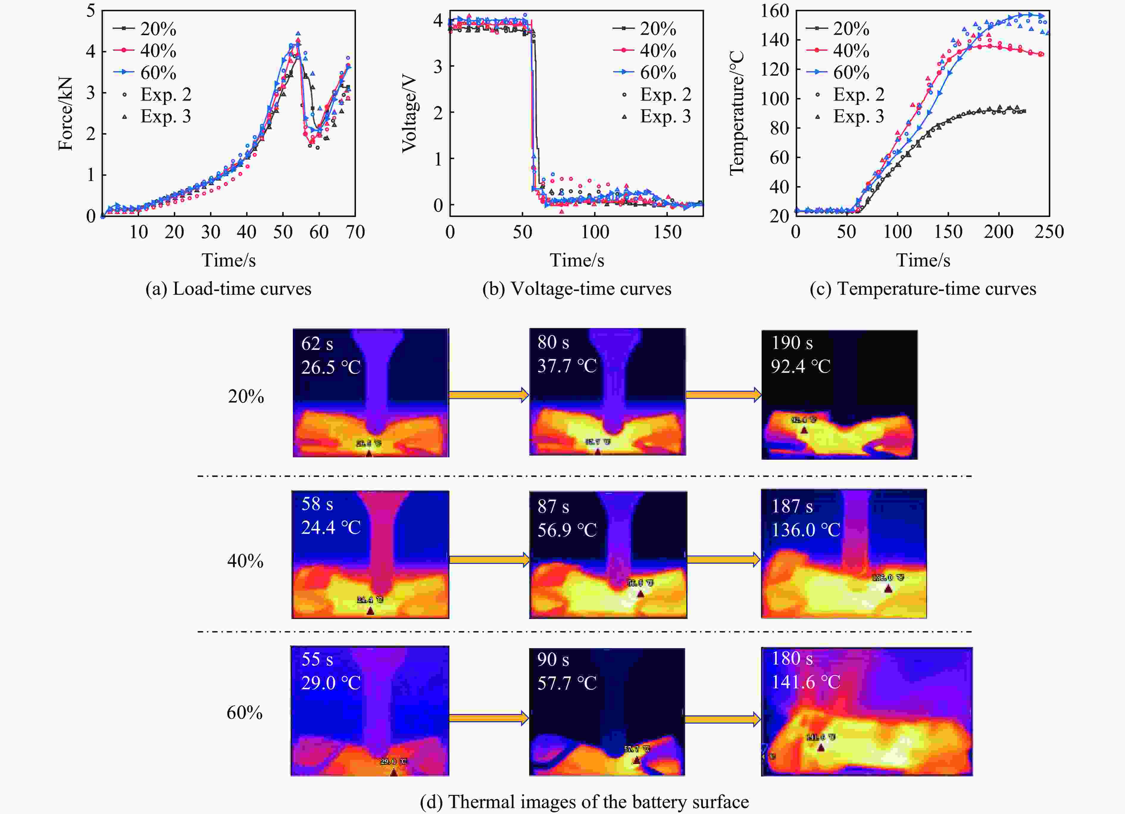
图 6 不同SOC下电池的力-电-热响应
Figure 6. Force-electric-thermal responses of the battery with different SOCs

图 7 不同加载速度下电池的力-电-热响应
Figure 7. Force-electric-thermal responses of the battery under different loading velocities

图 9 不同压痕位置工况下锂电池的力-电-热响应
Figure 9. Force-electric-thermal responses of the battery under different indentation locations

图 10 不同压痕位置工况下不同SOC的锂电池的热成像
Figure 10. Thermal images of lithium battery with different SOCs under different indentation positions

图 12 不同压头半径和SOC下锂电池的力-电响应特征
Figure 12. Force-electric response characteristics of batteries with different SOCs under different indenter radii conditions

图 13 不同压头半径和SOC下锂电池的温度特征
Figure 13. Temperature characteristics of lithium batteries with different SOCs under different indenter radii conditions
表 1 电池单体参数
Table 1. Battery parameters
Height/
mmDiameter/
mmNominal capacity/
(W·h)Nominal
voltage/VEnd-of-charge
voltage/VEnd-of-discharge
voltage/V65 18 4.6 3.7 4.2 2.75  下载: 导出CSV
表 2 实验条件与参数信息
Table 2. Information on experimental conditions and parameters
Exp. SOC/% Indenter velocity/
(mm·min−1)Displacement/
mmIndentation positions/
mmIndenter size/
mm1 100 10 13 30 5.0 2 20, 40, 60 10 13 30 5.0 3 40 2, 10, 20 13 30 5.0 4 20 10 13 10, 20, 30, 45, 55 5.0 5 20, 40, 60 10 13 30 5.0, 7.5, 10.0
下载: 导出CSV
-
[1] LAI X, JIN C Y, YI W, et al. Mechanism, modeling, detection, and prevention of the internal short circuit in lithium-ion batteries: recent advances and perspectives [J]. Energy Storage Materials, 2021, 35: 470–499. doi: 10.1016/j.ensm.2020.11.026 [2] PARLIKAR A, TRUONG C N, JOSSEN A, et al. The carbon footprint of island grids with lithium-ion battery systems: an analysis based on levelized emissions of energy supply [J]. Renewable and Sustainable Energy Reviews, 2021, 149: 111353. doi: 10.1016/j.rser.2021.111353 [3] HUANG L W, ZHANG Z S, WANG Z P, et al. Thermal runaway behavior during overcharge for large-format lithium-ion batteries with different packaging patterns [J]. Journal of Energy Storage, 2019, 25: 100811. doi: 10.1016/j.est.2019.100811 [4] FENG X N, OUYANG M G, LIU X, et al. Thermal runaway mechanism of lithium ion battery for electric vehicles: a review [J]. Energy Storage Materials, 2018, 10: 246–267. doi: 10.1016/j.ensm.2017.05.013 [5] HUANG W S, FENG X N, HAN X B, et al. Questions and answers relating to lithium-ion battery safety issues [J]. Cell Reports Physical Science, 2021, 2(1): 100285. doi: 10.1016/j.xcrp.2020.100285 [6] 李红刚, 张超, 曹俊超, 等. 锂离子电池碰撞安全仿真方法的研究进展与展望 [J]. 机械工程学报, 2022, 58(24): 121–144.LI H G, ZHANG C, CAO J C, et al. Advances and perspectives on modeling methods for collision safety of lithium-ion batteries [J]. Journal of Mechanical Engineering, 2022, 58(24): 121–144. [7] ZHOU D, LI H G, LI Z H, et al. Toward the performance evolution of lithium-ion battery upon impact loading [J]. Electrochimica Acta, 2022, 432: 141192. doi: 10.1016/j.electacta.2022.141192 [8] LI H G, ZHOU D, CAO J C, et al. On the damage and performance degradation of multifunctional sandwich structure embedded with lithium-ion batteries under impact loading [J]. Journal of Power Sources, 2023, 581: 233509. doi: 10.1016/j.jpowsour.2023.233509 [9] 郝鑫, 杜建华, 梁浩斌, 等. 锂离子电池冲击挤压后安全特性研究综述 [J]. 消防科学与技术, 2021, 40(7): 963–967. doi: 10.3969/j.issn.1009-0029.2021.07.003HAO X, DU J H, LIANG H B, et al. A review of the safety characteristics of lithium-ion batteries after impact extrusion [J]. Fire Science and Technology, 2021, 40(7): 963–967. doi: 10.3969/j.issn.1009-0029.2021.07.003 [10] 刘首彤, 黄沛丰, 白中浩. 锂离子电池机械滥用失效机理及仿真模型研究进展 [J]. 汽车工程, 2022, 44(4): 465–475.LIU S T, HUANG P F, BAI Z H. A review on research progress in failure mechanism and simulation model of li-ion battery related to mechanical abuse [J]. Automotive Engineering, 2022, 44(4): 465–475. [11] LIU B H, DUAN X D, YUAN C H, et al. Quantifying and modeling of stress-driven short-circuits in lithium-ion batteries in electrified vehicles [J]. Journal of Materials Chemistry A, 2021, 9(11): 7102–7113. doi: 10.1039/D0TA12082K [12] YUAN C H, GAO X, WONG H K, et al. A multiphysics computational framework for cylindrical battery behavior upon mechanical loading based on LS-DYNA [J]. Journal of the Electrochemical Society, 2019, 166(6): A1160. doi: 10.1149/2.1071906jes [13] ZHU X Q, WANG H, WANG X, et al. Internal short circuit and failure mechanisms of lithium-ion pouch cells under mechanical indentation abuse conditions: an experimental study [J]. Journal of Power Sources, 2020, 455: 227939. doi: 10.1016/j.jpowsour.2020.227939 [14] 董思捷, 张新春, 汪玉林, 等. 不同挤压载荷下圆柱形锂离子电池的失效机理试验研究 [J]. 中国机械工程, 2022, 33(8): 915–920. doi: 10.3969/j.issn.1004-132X.2022.08.005DONG S J, ZHANG X C, WANG Y L, et al. Experimental study of failure mechanism of cylindrical lithium-ion batteries under different compression loadings [J]. China Mechanical Engineering, 2022, 33(8): 915–920. doi: 10.3969/j.issn.1004-132X.2022.08.005 [15] VOYIADJIS G Z, AKBARI E, ŁUCZAK B, et al. Towards determining an engineering stress-strain curve and damage of the cylindrical lithium-ion battery using the cylindrical indentation test [J]. Batteries, 2023, 9(4): 233. doi: 10.3390/batteries9040233 [16] LI H G, ZHOU D, ZHANG M H, et al. Multi-field interpretation of internal short circuit and thermal runaway behavior for lithium-ion batteries under mechanical abuse [J]. Energy, 2023, 263: 126027. doi: 10.1016/j.energy.2022.126027 [17] LI H G, ZHOU D, DU C L, et al. Parametric study on the safety behavior of mechanically induced short circuit for lithium-ion pouch batteries [J]. Journal of Electrochemical Energy Conversion and Storage, 2021, 18(2): 020904. doi: 10.1115/1.4048705 [18] 范文杰, 薛鹏程, 王根伟, 等. 压缩载荷作用下锂离子电池的安全性能 [J]. 高压物理学报, 2019, 33(6): 065901. doi: doi:10.11858/gywlxb.20190752FAN W J, XUE P C, WANG G W, et al. Safety performance of power lithium ion battery under compressive load [J]. Chinese Journal of High Pressure Physics, 2019, 33(6): 065901. doi: doi:10.11858/gywlxb.20190752 [19] WANG Q S, MAO B B, STOLIAROV S I, et al. A review of lithium-ion battery failure mechanisms and fire prevention strategies [J]. Progress in Energy and Combustion Science, 2019, 73: 95–131. doi: 10.1016/j.pecs.2019.03.002 [20] PAN Z X, SEDLATSCHEK T, XIA Y. Effect of state-of-charge and air exposure on tensile mechanical properties of lithium-ion battery electrodes [J]. Journal of The Electrochemical Society, 2020, 167(9): 090517. doi: 10.1149/1945-7111/ab8804 [21] DUAN X D, WANG H C, JIA Y K, et al. A multiphysics understanding of internal short circuit mechanisms in lithium-ion batteries upon mechanical stress abuse [J]. Energy Storage Materials, 2022, 45: 667–679. doi: 10.1016/j.ensm.2021.12.018 [22] LI H G, LIU B H, ZHOU D, et al. Coupled mechanical-electrochemical-thermal study on the short-circuit mechanism of lithium-ion batteries under mechanical abuse [J]. Journal of the Electrochemical Society, 2020, 167(12): 120501. doi: 10.1149/1945-7111/aba96f -

 下载:
下载:


计量
- 文章访问数: 680
- HTML全文浏览量: 520
- PDF下载量: 42
