


Coupling Inhibition Effects of Dry Water Modified by Potassium Carbonate and Hexafluoropropane on Methane Explosion
-
摘要: 爆炸抑制技术是减轻瓦斯爆炸事故灾后影响的重要手段。为探究两相复合抑爆剂的抑制效果,选取碳酸钾改性干水粉体和六氟丙烷(C3H2F6)气体为抑爆介质,通过试验研究了二者复配影响下甲烷爆炸压力和时间参数的变化规律,并对其协同抑爆机理开展了理论分析。试验结果表明,在富燃工况下,甲烷爆炸的快速燃爆时间和持续燃烧时间随着碳酸钾改性干水和C3H2F6配比的增加而增加,碳酸钾改性干水大幅提升了C3H2F6的抑制效果。贫燃、化学当量比和富燃工况下,气-固两相抑制剂的临界抑爆配比分别为5%-6 g、3%-6 g、1%-4 g。理论分析结果显示:复配抑爆剂对甲烷爆炸的物理抑制作用表现为稀释可燃物浓度、降低反应体系温度和稀释氧浓度;化学抑制作用方面,碳酸钾和C3H2F6热解产生的KCO3、KOH、OH和含氟基团降低了甲烷爆炸链式反应产生的关键自由基浓度。研究结果可为清洁抑爆材料及相应抑爆技术的研发提供理论依据。Abstract: Explosion suppression technology plays a vital role in reducing the hazardous effect of gas explosion incidents. This study aimed to investigate the explosion suppression effect of two-phase composite inhibitor mixtures of hexafluoropropane and dry water modified by potassium carbonate. The explosion pressure and time parameters of methane-air mixtures were obtained experimentally. Then the synergistic mechanisms on methane explosion suppression was analyzed theoretically. Results of the experiments shows that the combustion time of methane-air mixtures increase with the rising ratio of dry water modified by potassium carbonate in the coupled inhibitors. Dry water modified by potassium carbonate greatly enhanced the explosion suppression effect of C3H2F6. The critical inhibition ratios of gas-solid inhibitors are 5%-6 g, 3%-6 g, and 1%-4 g for fuel-lean, stoichiometric, and fuel-rich methane-air mixtures, respectively. Moreover, the physical inhibition effects of the dilution in the premixed mixtures and the reduction in the flame temperature, as well as the chemical suppression effect, synergistically inhibit the deflagration of methane-air mixtures. In terms of the chemical inhibition, it is KCO3, KOH, OH and fluorine-containing groups that produced by the pyrolysis of potassium carbonate and C3H2F6 reduce the concentration of key radicals of methane explosion. The results of the work will help to providing the theoretical basis for the development of more effective explosion-suppressant and promoting the related explosion-suppressing technology.
-
图 1 20 L球形爆炸试验系统示意图
Figure 1. Schematic diagram of the 20 L spherical explosion test system
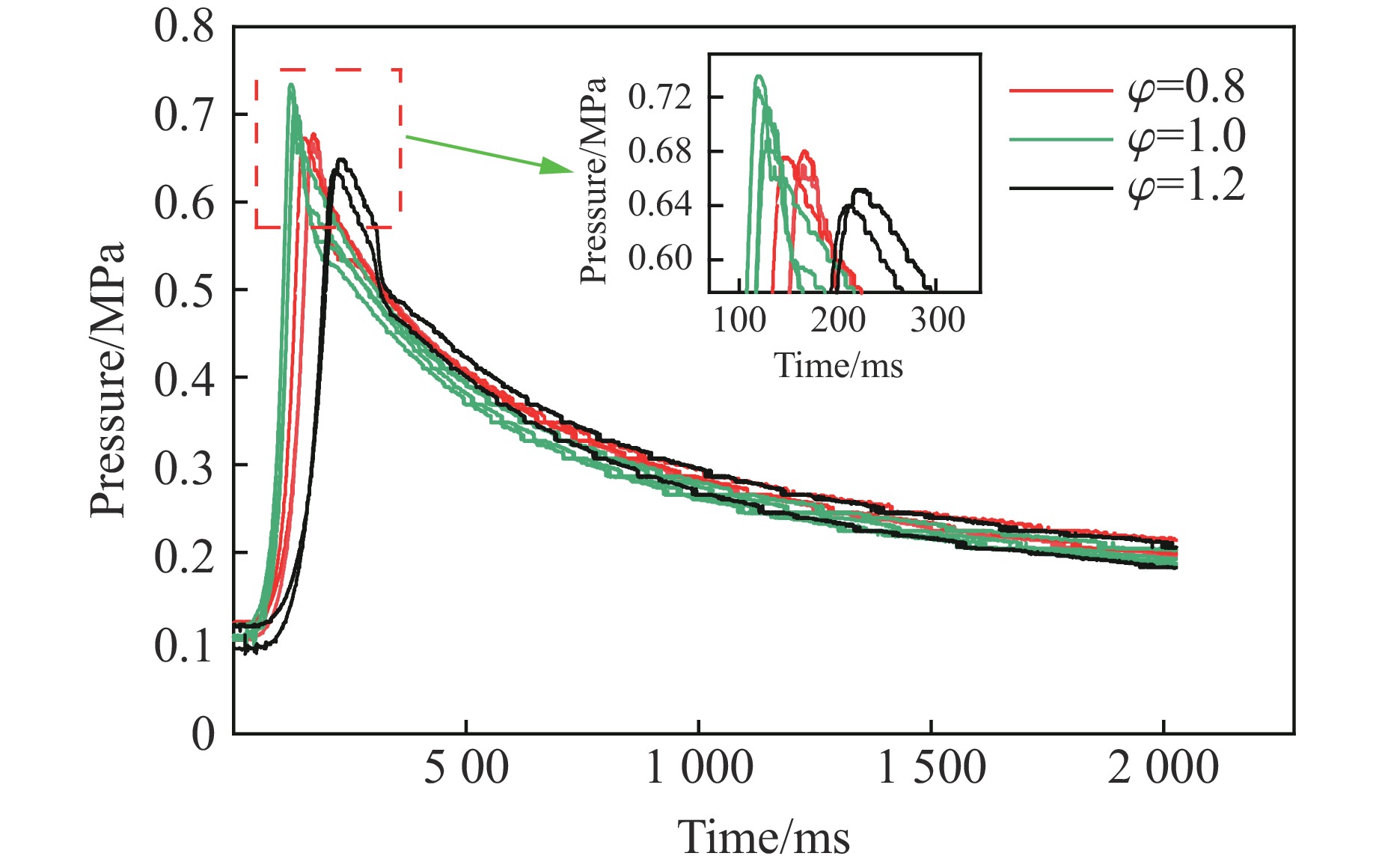
图 3 甲烷/空气预混气体在3种化学计量比下爆燃的压力-时间演化曲线
Figure 3. Pressure-time evolution curves of methane/air premixed gas deflagration at three equivalence ratios
图 4 复配抑爆剂抑制甲烷的最大爆炸压力
Figure 4. Maximum pressure of methane inhibited by composite suppressants
图 5 复配抑爆剂抑制甲烷的最大爆炸压力上升速率
Figure 5. Maximum pressure rising rate of methane inhibited by composite suppressants
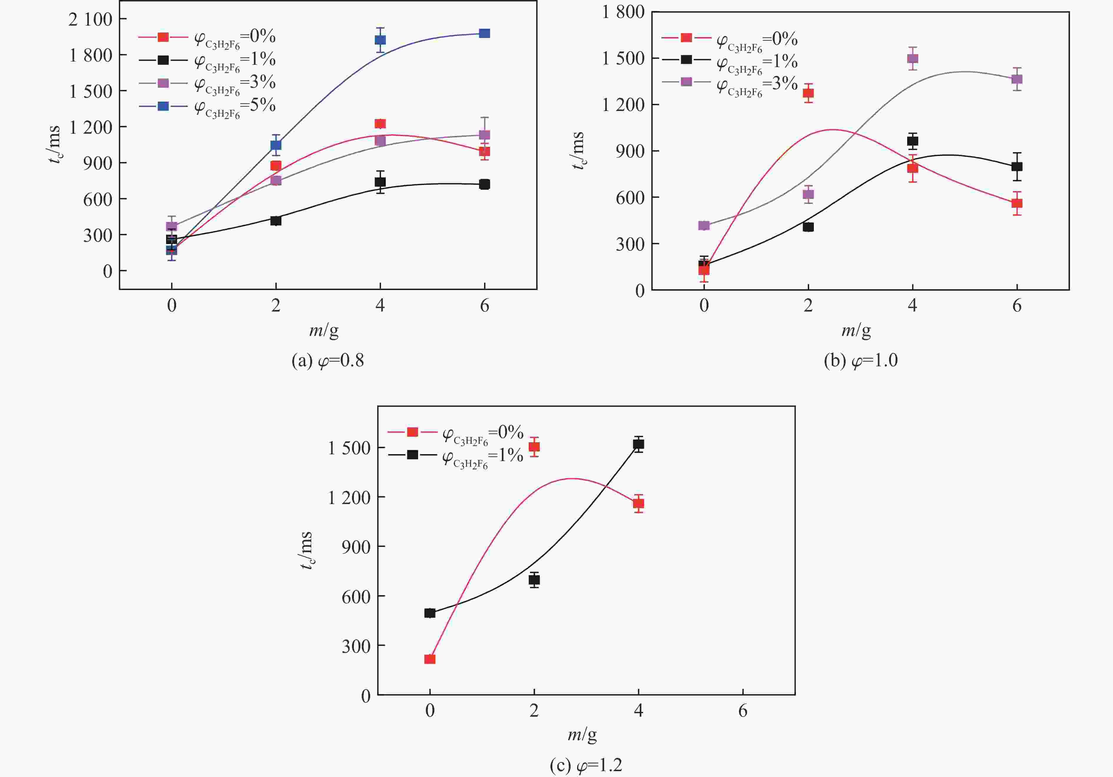
图 6 复配抑爆剂对甲烷爆炸压力峰值时间的抑制规律
Figure 6. Peak pressure time of methane inhibited by composite suppressants

图 7 复配抑爆剂对甲烷爆炸升压速率峰值时间的抑制规律
Figure 7. Peak pressure rising rate time of methane inhibited by composite suppressants
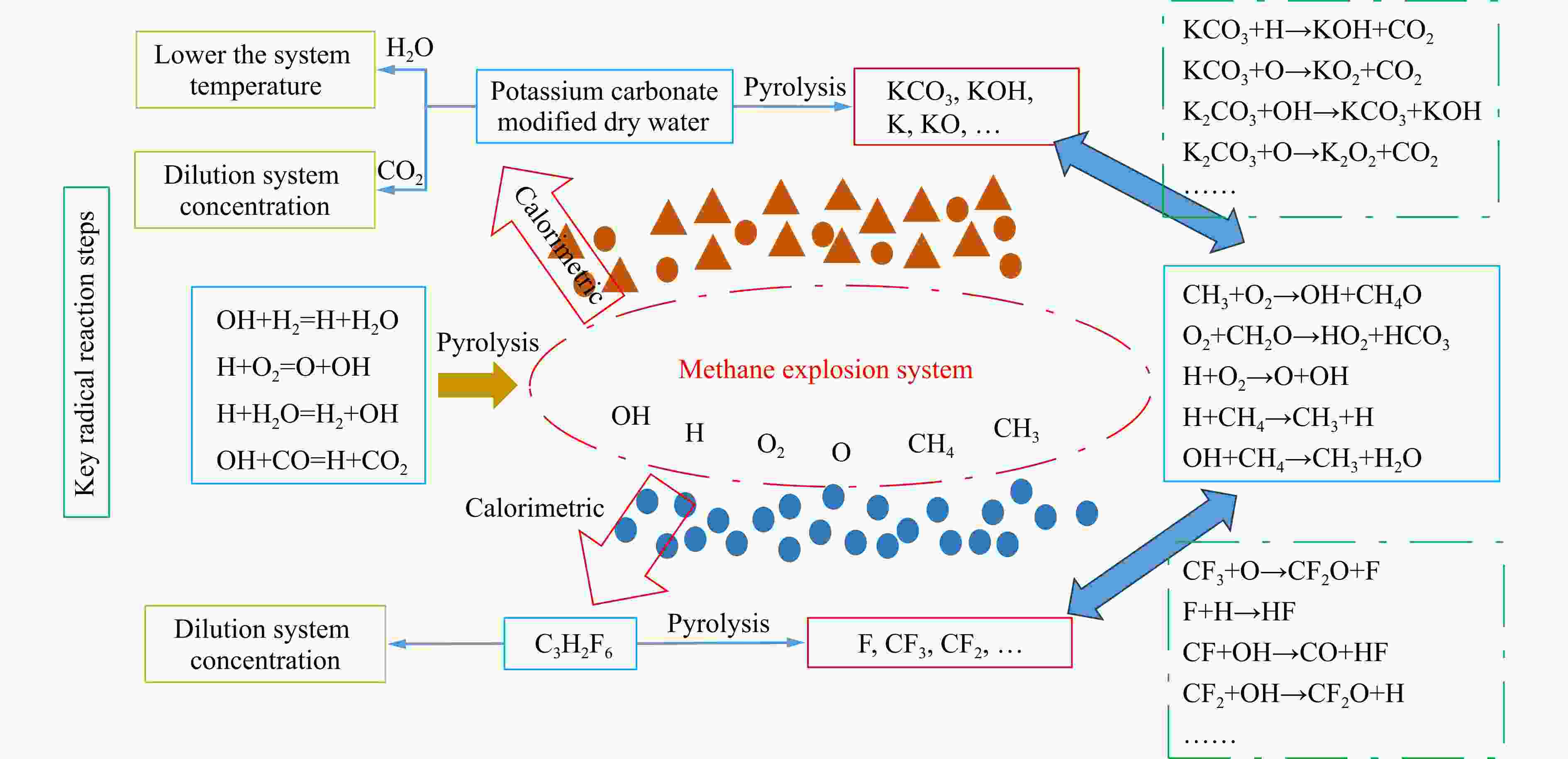
图 8 碳酸钾改性干水-C3H2F6对甲烷爆炸的作用示意图
Figure 8. Explosion inhibition mechanism of the dry water modified by potassium carbonate-C3H2F6 mixtures
表 1 试验工况
Table 1. Test conditions
Compounding ratios $\varphi_{{\rm{C}_3} {{\rm{H}_2}}{{\rm{F}_6}}} $/% m/g Compounding ratios $\varphi_{{\rm{C}_3} {{\rm{H}_2}}{{\rm{F}_6}}} $/% m/g 1%-2 g 1 2 5%-2 g 5 2 1%-4 g 1 4 5%-4 g 5 4 1%-6 g 1 6 5%-6 g 5 6 3%-2 g 3 2 7%-2 g 7 2 3%-4 g 3 4 7%-4 g 7 4 3%-6 g 3 6 7%-6 g 7 6  下载: 导出CSV
表 2 复配抑爆工况及抑爆结果
Table 2. Coupling inhibition conditions and the corresponding test results
Compounding ratio Test results ϕ=0.8 ϕ=1.0 ϕ=1.2 1%-2 g Exploded Exploded Exploded 1%-4 g Exploded Exploded Exploded 1%-6 g Exploded Exploded Unexploded 3%-2 g Exploded Exploded Unexploded 3%-4 g Exploded Exploded Unexploded 3%-6 g Exploded Exploded Unexploded 5%-2 g Exploded Unexploded Unexploded 5%-4 g Exploded Unexploded Unexploded 5%-6 g Exploded Unexploded Unexploded 7%-2 g Unexploded Unexploded Unexploded
下载: 导出CSV
表 3 抑制甲烷爆炸的临界配比
Table 3. Critical compounding ratios for methane explosion suppression
ϕ $\varphi_{{\rm{C}_3} {{\rm{H}_2}}{{\rm{F}_6}}} $/% Critical compounding ratio 0.8 10 5%-6 g 1.0 7 3%-6 g 1.2 4 1%-4 g
下载: 导出CSV
Reactions Indexing factor Ea/(J·mol−1) KCO3+H=KOH+CO2 3×10¹² 70 040.2 KCO3+O=KO2+CO2 5×10¹² 52 509.2 KHCO3+KO=K2CO3+OH 6×10¹² 122 549.4 KHCO3+KOH=K2CO3+H2O 3×10¹² 157 569.4 KCO3+KO=K2CO3+O 7×10¹² 87 529.3 KCO3+KO2=K2CO3+O2 1×10¹³ 52 509.2 K2CO3+M=K2O+CO2+M 5×10¹⁶ 1 417 957.6 K2CO3+OH=KCO3+KOH 3×10¹⁴ 192 547.7 K2CO3+O=K2O2+CO2 3×10¹⁴ 192 547.7
下载: 导出CSV
-
[1] 邓军, 周佳敏, 白祖锦, 等. 瓦斯对煤低温氧化过程微观结构及热反应性的影响研究 [J]. 煤炭科学技术, 2023, 51(1): 304–312.DENG J, ZHOU J M, BAI Z J, et al. Effect of gas on microstructure and thermal reactivity of coal during low temperature oxidation [J]. Coal Science and Technology, 2023, 51(1): 304–312. [2] FAN W P, GAO Y, ZHANG Y M, et al. Experimental studies and modeling on flame velocity in turbulent deflagration in an open tube [J]. Process Safety and Environmental Protection, 2019, 129: 291–307. doi: 10.1016/j.psep.2019.07.013 [3] HUANG L J, WANG Y, PEI S F, et al. Effect of elevated pressure on the explosion and flammability limits of methane-air mixtures [J]. Energy, 2019, 186: 115840. doi: 10.1016/j.energy.2019.07.170 [4] SUN X X, LU S X. On the mechanisms of flame propagation in methane-air mixtures with concentration gradient [J]. Energy, 2020, 202: 117782. doi: 10.1016/j.energy.2020.117782 [5] YI W, WEN X P, GUO Z D, et al. Experimental study on the propagation characteristics of hydrogen/methane/air premixed flames in a narrow channel [J]. International Journal of Hydrogen Energy, 2022, 47(9): 6377–6387. doi: 10.1016/j.ijhydene.2021.12.019 [6] SKŘÍNSKÝ J, OCHODEK T, VEREŠ J, et al. The effect of low temperature on the explosion characteristics of a methane/air mixtures [J]. Energy Reports, 2022, 8(Suppl 15): 303–308. [7] 程方明, 南凡, 罗振敏, 等. 瓦斯抑爆材料及机理研究进展与发展趋势 [J]. 煤炭科学技术, 2021, 49(8): 114–124.CHENG F M, NAN F, LUO Z M, et al. Research progress and development trend of gas explosion suppression materials and mechanism [J]. Coal Science and Technology, 2021, 49(8): 114–124. [8] JI H, LU R J, YANG K, et al. Experimental study on methane explosion suppression by heptafluoropropane drived modified ABC powder [J]. Process Safety and Environmental Protection, 2023, 170: 623–635. doi: 10.1016/j.psep.2022.12.031 [9] WANG T, YANG P, YI W Z, et al. Effect of obstacle shape on the deflagration characteristics of premixed LPG-air mixtures in a closed tube [J]. Process Safety and Environmental Protection, 2022, 168: 248–256. doi: 10.1016/j.psep.2022.09.079 [10] 裴蓓, 李世梁, 韦双明, 等. N2/超细水雾抑制甲烷爆炸点火和火焰传播特性 [J]. 中国矿业大学学报, 2023, 52(2): 329–341.PEI B, LI S L, WEI S M, et al. Inhibition effect on the ignition and flame propagation characteristic of methane explosion by N2/ultrafine water mist [J]. Journal of China University of Mining & Technology, 2023, 52(2): 329–341. [11] 杨克, 张平, 邢志祥, 等. 含NaCl超细水雾抑制甲烷爆炸实验研究 [J]. 中国安全生产科学技术, 2019, 15(3): 86–91. doi: 10.11731/j.issn.1673-193x.2019.03.014YANG K, ZHANG P, XING Z X, et al. Experimental study on methane explosion suppression by ultrafine water mist containing NaCl additive [J]. Journal of Safety Science and Technology, 2019, 15(3): 86–91. doi: 10.11731/j.issn.1673-193x.2019.03.014 [12] LIU R Z, ZHANG M C, JIA B S. Application of gas explosion nanometer powder suppression material in coal mine safety [J]. Integrated Ferroelectrics, 2021, 217(1): 240–254. doi: 10.1080/10584587.2021.1911317 [13] 覃欣欣, 司荣军, 李润之. 抑爆剂面密度对瓦斯爆炸传播抑制效果的影响 [J]. 煤矿安全, 2016, 47(12): 168–171.QIN X X, SI R J, LI R Z. Influence of surface density of explosion suppression agent on inhibiting effect of gas explosion propagation [J]. Safety in Coal Mines, 2016, 47(12): 168–171. [14] LUO Z M, SUN Y L, WANG T, et al. Synergistic inhibition of H2/CH4 explosions by CO2/modified KHCO3 powder [J]. Journal of Loss Prevention in the Process Industries, 2023, 86: 105197. doi: 10.1016/j.jlp.2023.105197 [15] ZHENG L G, WANG Y L, YU S J, et al. The premixed methane/air explosion inhibited by sodium bicarbonate with different particle size distributions [J]. Powder Technology, 2019, 354: 630–640. doi: 10.1016/j.powtec.2019.06.034 [16] 纪文涛, 张国涛, 杨帅帅, 等. 惰性粉体抑制瓦斯/煤尘复合爆炸特性及机理研究 [J]. 煤炭科学技术, 2024, 52(11): 337–345. doi: 10.12438/cst.2023-1411JI W T, ZHANG G T, YANG S S, et al. Study on the characteristics and mechanism of inert powder inhibition of gas/coal dust compound explosion [J]. Coal Science and Technology, 2024, 52(11): 337–345. doi: 10.12438/cst.2023-1411 [17] YANG K, LI L K, JI H, et al. Experimental study of NaHCO3/modified vermiculite composite powder for methane explosion suppression [J]. Fuel, 2024, 378: 132808. doi: 10.1016/j.fuel.2024.132808 [18] CHEN J S, CHEN K, SHI W X, et al. The preparation of novel core-shell suppressor and its suppression mechanism on coal dust explosion flame [J]. Fuel, 2022, 313: 122997. doi: 10.1016/j.fuel.2021.122997 [19] CHEN X F, FAN A, YUAN B H, et al. Renewable biomass gel reinforced core-shell dry water material as novel fire extinguishing agent [J]. Journal of Loss Prevention in the Process Industries, 2019, 59: 14–22. doi: 10.1016/j.jlp.2019.02.008 [20] TIAN S Y, QIN B T, MA D, et al. Suppressive effects of alkali metal salt modified dry water material on methane-air explosion [J]. Energy, 2023, 285: 129547. doi: 10.1016/j.energy.2023.129547 [21] LEE E, SON H, CHOI Y. Elucidating the effects of particle sizes on the fire extinguishing performance of core-shell dry water [J]. Korean Journal of Chemical Engineering, 2020, 37(10): 1642–1648. doi: 10.1007/s11814-020-0632-0 [22] 吴佩利. 改性干水粉体制备及灭火性能研究 [D]. 西安: 西安科技大学, 2022.WU P L. Study on preparation and fire extinguishing performance of modified dry water powder [D]. Xi’an: Xi’an University of Science and Technology, 2022. [23] WANG Q H, MA C, DENG J, et al. Gas explosion suppression by ammonium dihydrogen phosphate-modified dry water powder [J]. Powder Technology, 2023, 416: 118228. doi: 10.1016/j.powtec.2023.118228 [24] ZHENG X Z, KOU Z Z, LIU S K, et al. Preparation and properties of a new core-shell-modified gel dry-water powder [J]. Powder Technology, 2023, 422: 118493. doi: 10.1016/j.powtec.2023.118493 [25] WANG T, YANG Z, YANG P, et al. The deflagration suppression effect of ammonium salt-modified dry water on methane-air mixtures: an experimental investigation [J]. Powder Technology, 2024, 434: 119313. doi: 10.1016/j.powtec.2023.119313 [26] 程方明, 南凡, 肖旸, 等. CF3I和CO2抑制甲烷-空气爆炸实验研究 [J]. 爆炸与冲击, 2022, 42(6): 065402. doi: 10.11883/bzycj-2021-0386CHENG F M, NAN F, XIAO Y, et al. Experimental study on the suppression of methane-air explosion by CF3I and CO2 [J]. Explosion and Shock Waves, 2022, 42(6): 065402. doi: 10.11883/bzycj-2021-0386 [27] LIANG H, YAN X Q, SHI E H, et al. Flame evolution and pressure dynamics of premixed stoichiometric ammonia/hydrogen/air in a closed duct [J]. Fuel, 2024, 363: 130983. doi: 10.1016/j.fuel.2024.130983 [28] 王保. 20 L球内惰气抑制甲烷-乙烯与空气预混爆炸特性研究 [D]. 淮南: 安徽理工大学, 2022.WANG B. Study on the performance of 20 L inert gas in a sphere to suppress the premixed explosion of methane-ethylene with air [D]. Huainan: Anhui University of Science and Technology, 2022. [29] 王燕, 林森, 李忠, 等. 惰性气体对KHCO3冷气溶胶甲烷抑爆性能的影响研究 [J]. 煤炭科学技术, 2021, 49(2): 145–152.WANG Y, LIN S, LI Z, et al. Research on synergistic effect of inert gas on methane explosion suppression performance of KHCO3 cold aerosol [J]. Coal Science and Technology, 2021, 49(2): 145–152. [30] DONG Z Q, LIU L J, CHU Y Y, et al. Explosion suppression range and the minimum amount for complete suppression on methane-air explosion by heptafluoropropane [J]. Fuel, 2022, 328: 125331. doi: 10.1016/j.fuel.2022.125331 [31] 杨克, 陈舒佳, 邢志祥, 等. 七氟丙烷与障碍物对甲烷爆炸耦合影响的试验研究 [J]. 中国矿业大学学报, 2023, 52(4): 750–760.YANG K, CHEN S J, XING Z X, et al. Experimental study of the coupling effect of heptafluoropropane and obstacle on the methane explosion [J]. Journal of China University of Mining and Technology, 2023, 52(4): 750–760. [32] 王涛, 董哲, 盛禹淮, 等. 卤代烷气体灭火剂促进-抑制瓦斯燃爆特性试验 [J]. 煤炭科学技术, 2024, 52(4): 265–274. doi: 10.12438/cst.2023-1793WANG T, DONG Z, SHENG Y H, et al. Experiment on the promoting-inhibiting effects on methane explosion by using haloalkanes [J]. Coal Science and Technology, 2024, 52(4): 265–274. doi: 10.12438/cst.2023-1793 [33] 孟祥卿. 气/固两相抑制剂的甲烷抑爆特性研究 [D]. 焦作: 河南理工大学, 2019.MENG X Q. Suppression characteristics of gas/solid two-phase inhibitors on methane explosion [D]. Jiaozuo: Henan Polytechnic University, 2019. [34] ZHAO T L, CHEN X K, LUO Z M, et al. Effect of N2 inerting on the inhibition of methane explosions by a multicomponent powder [J]. Fuel, 2023, 337: 127203. doi: 10.1016/j.fuel.2022.127203 [35] 田志辉. 气-固混合抑制剂对矿井瓦斯的抑爆实验研究 [D]. 西安: 西安科技大学, 2013.TIAN Z H. Suppressing experimental study on mine methane explosion by the gas-solid mixied inhibitors [D]. Xi’an: Xi’an University of Science and Technology, 2013. [36] LUO Z M, WANG T, TIAN Z H, et al. Experimental study on the suppression of gas explosion using the gas-solid suppressant of CO2/ABC powder [J]. Journal of Loss Prevention in the Process Industries, 2014, 30: 17–23. doi: 10.1016/j.jlp.2014.04.006 [37] BABUSHOK V I, LINTERIS G T, HOORELBEKE P, et al. Flame inhibition by potassium-containing compounds [J]. Combustion Science and Technology, 2017, 189(12): 2039–2055. doi: 10.1080/00102202.2017.1347162 [38] FERGUSON J D, JOHNSON N L, KEKENES-HUSKEY P M, et al. Unimolecular rate constants for HX or DX elimination (X=F, Cl) from chemically activated CF3CH2CH2Cl, C2H5CH2Cl, and C2D5CH2Cl: threshold energies for HF and HCl elimination [J]. The Journal of Physical Chemistry A, 2005, 109(20): 4540–4551. doi: 10.1021/jp040735g [39] 谈玲华, 李勤华, 冒爱琴, 等. 六氟丙烷热分解性能及机理研究 [J]. 南京理工大学学报(自然科学版), 2010, 34(5): 691–695.TAN L H, LI Q H, MAO A Q, et al. Thermal decomposition properties and mechanism of hexafluoropropane [J]. Journal of Nanjing University of Science and Technology (Natural Science), 2010, 34(5): 691–695. [40] BARRY J, LOCKE G, SCOLLARD D, et al. 1,1,1,3,3,-pentafluorobutane (HFC-365mfc): atmospheric degradation and contribution to radiative forcing [J]. International Journal of Chemical Kinetics, 1997, 29(8): 607–617. doi: 10.1002/(SICI)1097-4601(1997)29:8<607::AID-KIN6>3.0.CO;2-Y -

 下载:
下载:

计量
- 文章访问数: 713
- HTML全文浏览量: 366
- PDF下载量: 39
