


Effects of Shock Peak Stress and Pulse Duration on Spall Damage of NbTiZr Medium-Entropy Alloy
-
摘要: 中、高熵合金因很好地兼顾了强度和韧性而备受关注,在多种极端工况下具有重要的应用前景。然而,在强冲击载荷等极端条件下,其动态力学行为和损伤失效机制仍不清楚。为此,研究了NbTiZr中熵合金在平板冲击载荷下的层裂损伤,探讨了冲击应力和加载脉宽的影响。通过波剖面分析,获得了冲击应力、加载脉宽和层裂强度信息。研究表明,NbTiZr中熵合金的层裂强度随冲击应力的增大而线性增大,随加载脉冲宽度的增大呈指数减小,介于3.77~4.80 GPa之间。利用光学显微镜、扫描电子显微镜和电子背散射衍射,分析了冲击加载后回收样品的微观组织结构,发现冲击应力和加载脉冲宽度对NbTiZr的层裂损伤形貌有显著影响,层裂损伤形式为准解理断裂,未观察到固-固相变或变形孪晶。Abstract: Dynamic mechanical behaviors of high entropy alloys (HEAs) or medium-entropy alloys (MEAs) have attracted significant attention due to their exceptional strength-toughness balance and promising potential applications in extreme conditions. This work investigates the effects of peak shock stress and pulse duration on the spall damage of the NbTiZr MEA under dynamic shock loading. Peak shock stresses, pulse durations and spall strengths are determined by analyzing free surface velocity profiles, with postmortem microstructural analysis to reveal the underlying deformation and failure mechanisms. The measured spall strength of NbTiZr MEA ranges from 3.77 GPa to 4.80 GPa, showing minimal dependence on the peak shock stress but high sensitivity to the pulse duration. Furthermore, the damage morphologies are significantly influenced by pulse durations. The damage is recognized as a quasi-cleavage fracture mode. No phase transition or deformation twins are observed within the recovered NbTiZr alloy.
-
Key words:
- NbTiZr /
- spall damage /
- shock loading history /
- microstructure
-
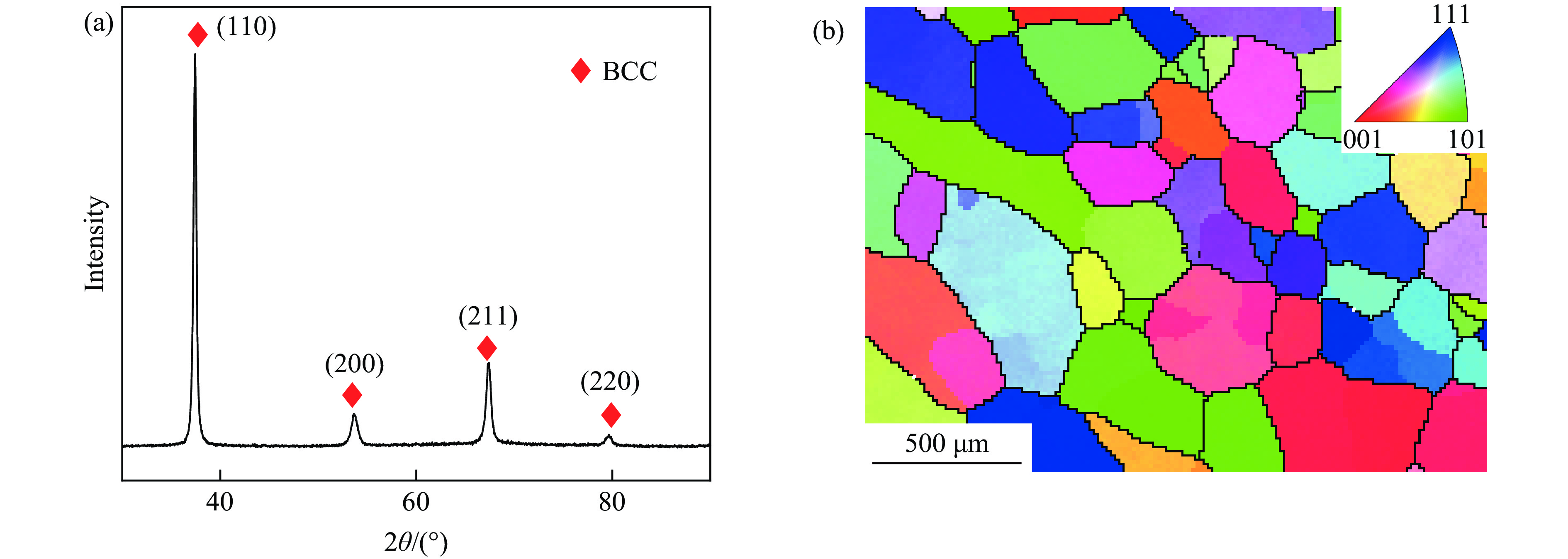
图 1 初始NbTiZr中熵合金样品的XRD谱(a)和反极图(b)
Figure 1. XRD pattern (a) and inverse pole figure (b) of the as-cast NbTiZr medium-entropy alloy sample
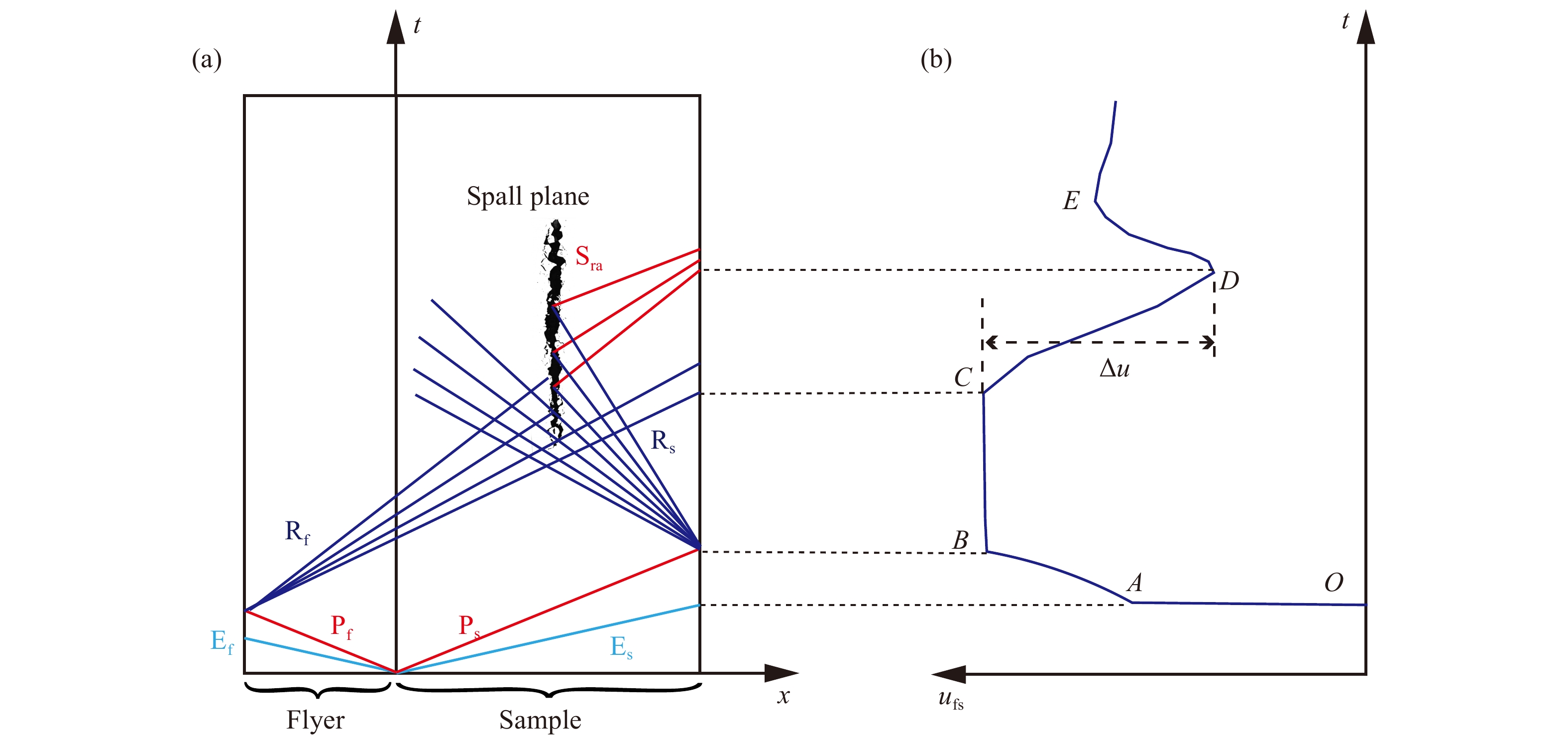
图 2 平板冲击实验的波系作用(a)及其对应的自由面速度曲线(b)
Figure 2. Schematic x-t (position-time) diagrams of wave propagation and interaction (a) and corresponding free surface velocity profiles ufs(t) (b)
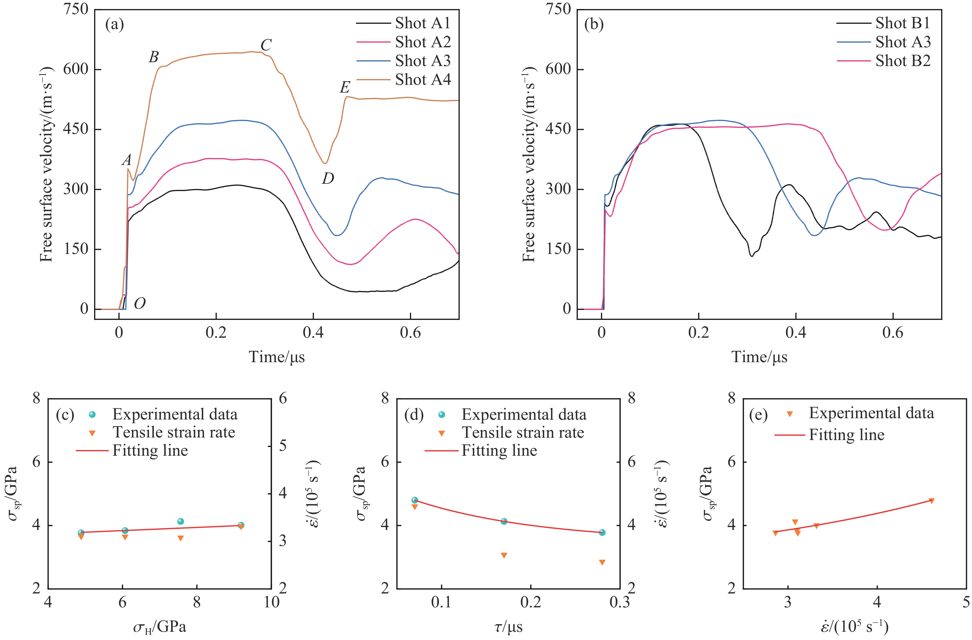
图 3 不同冲击应力(a)和冲击脉宽(b)条件下的自由面速度历史曲线以及层裂强度与冲击峰值应力(c)、冲击脉宽(d)和拉伸应变率(e)的拟合关系
Figure 3. Free surface velocity profiles for different peak stresses (a) and different pulse durations (b), and the spall strength as a function of peak stress (c), pulse duration (d) and tensile strain rate (e)
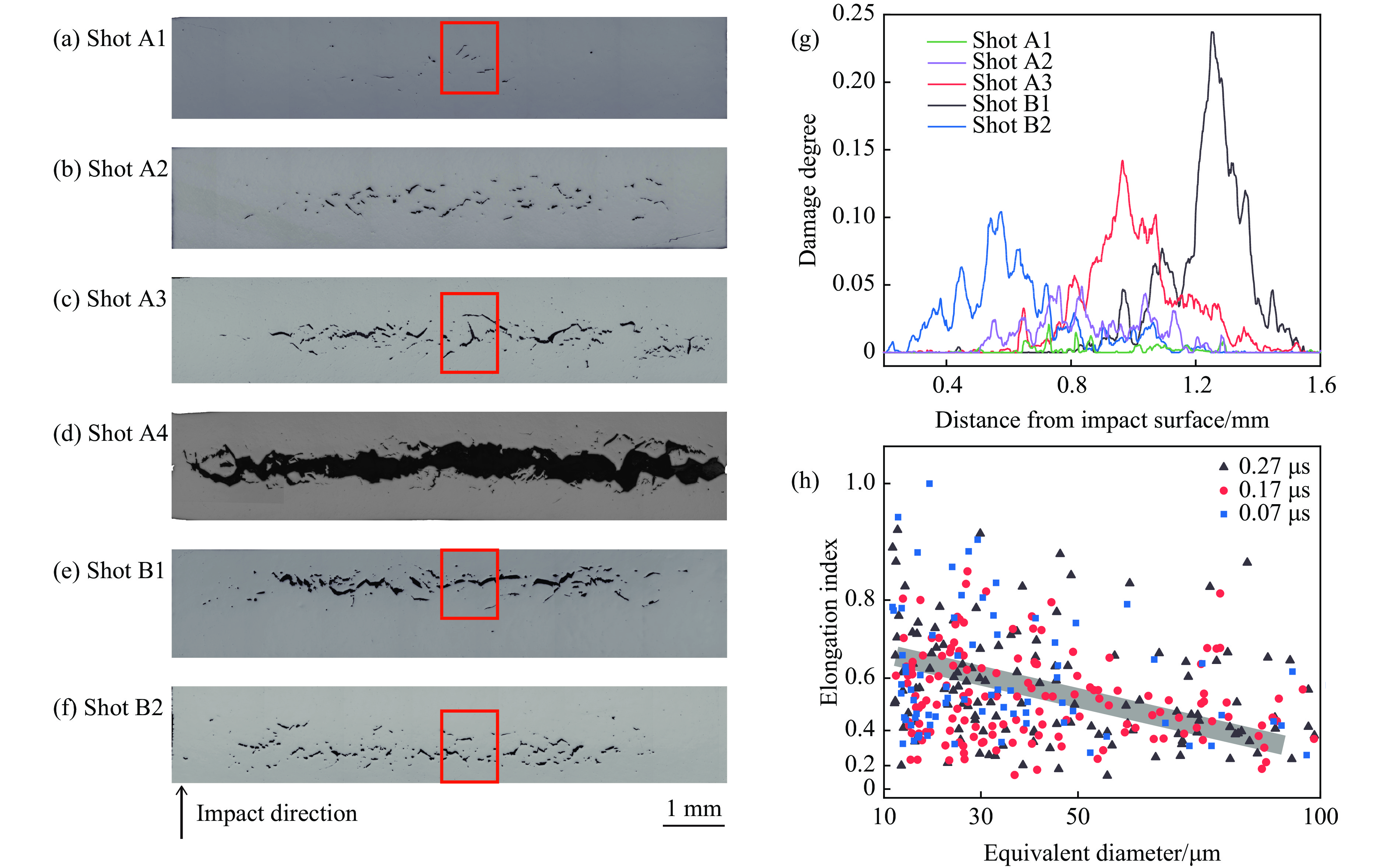
图 4 平板冲击实验得到的回收样品的OM图像:(a)~(d) 不同冲击应力下的层裂损伤形貌,(e)~(f) 不同加载脉冲宽度下的层裂损伤形貌,(g) 沿冲击方向的损伤度分布统计(Shot A4除外),(h) 不同加载脉冲宽度下层裂损伤的伸长率指数与孔洞及裂纹等效尺寸的关系
Figure 4. Optical graphs of the recovered samples and damage degree analysis: (a)−(d) damage of samples for different peak stresses, and (e)−(f) damage of samples for different pulse durations; (g) damage degree distributions along the impact direction for all shots except Shot A4; (h) elongation index as a function of equivalent diameter of voids and cracks with different pulse durations
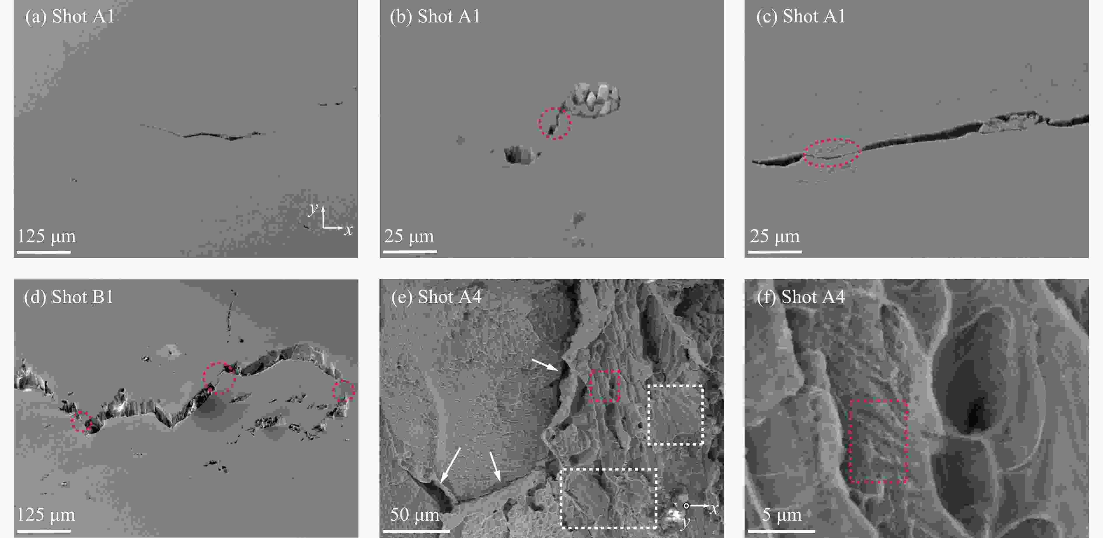
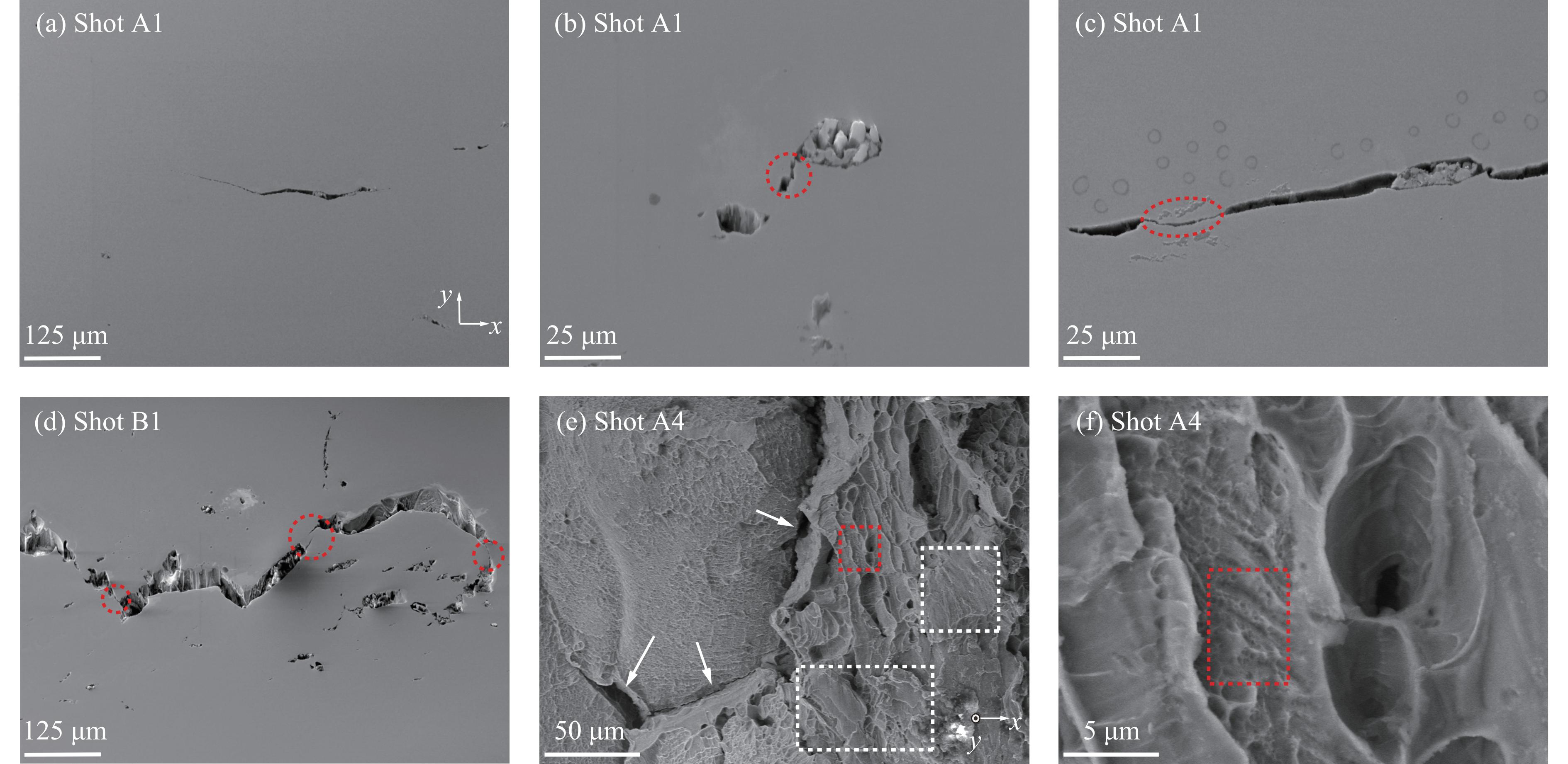
图 5 回收样品层裂损伤的SEM图像:(a)~(c) Shot A1的回收样品,(d) Shot B1的回收样品,(e) Shot A4的回收样品层裂面断口形貌,(f) 图5(e)红框区域的局部放大图像(冲击方向为y轴)
Figure 5. SEM images of damage in the spallation region: (a)−(c) recovered sample in Shot A1, (d) recovered sample in Shot B1, (e) fracture morphology of the spall plane of the recovered sample in Shot A4, (f) magnified view of the region indicated by the red rectangle in Fig.5(e) (The impact direction is the y-axis.)
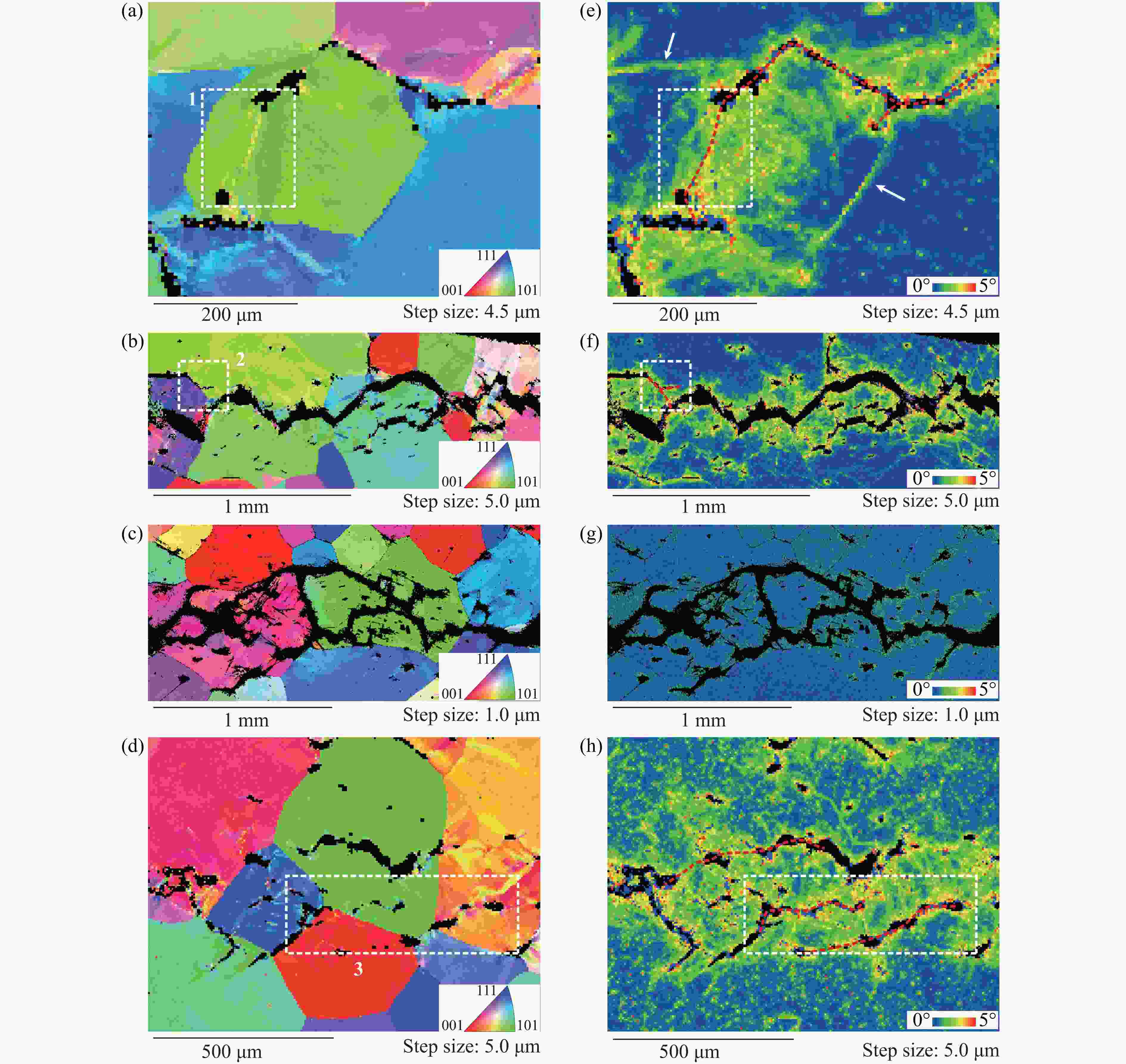
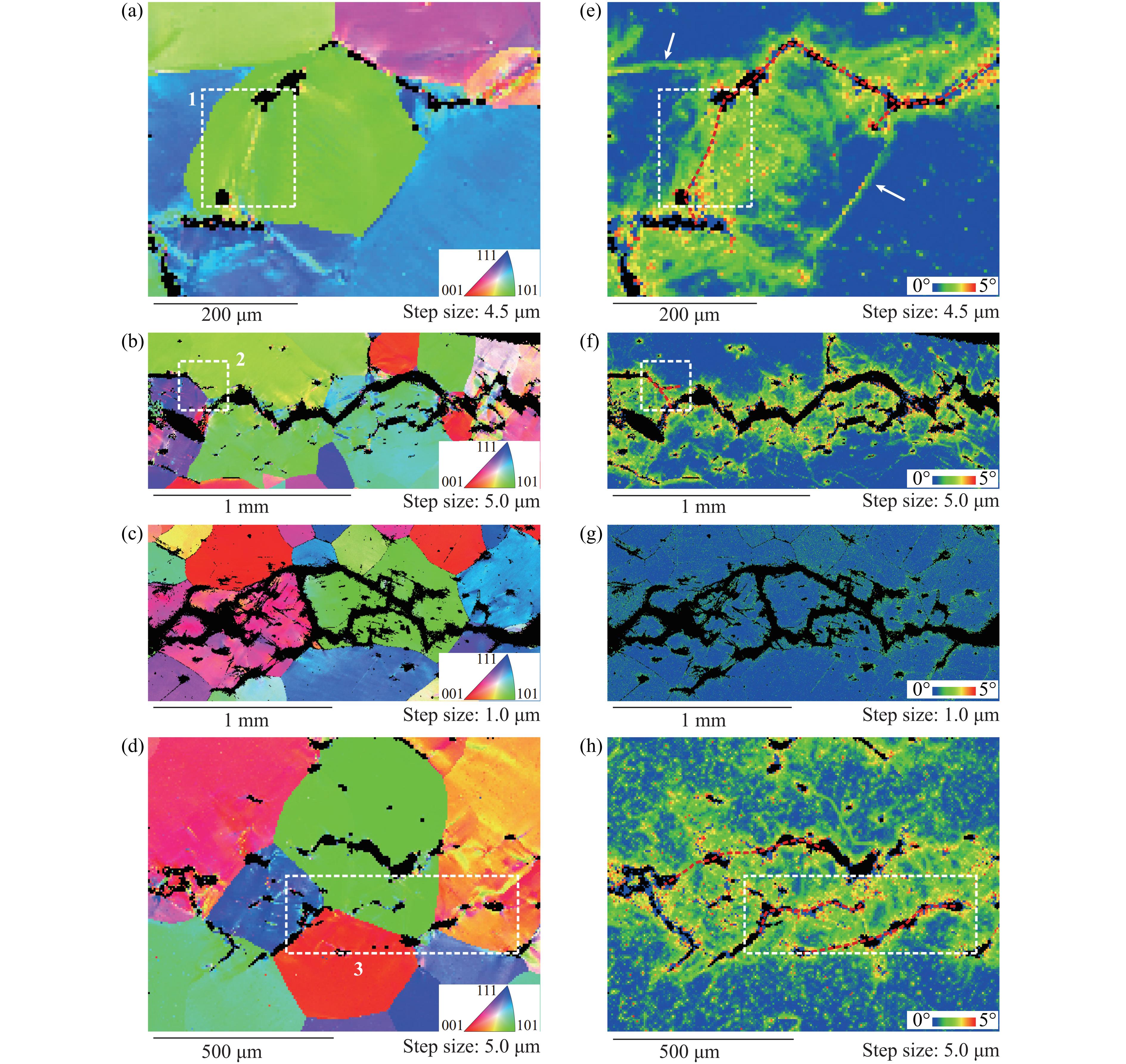
图 6 Shot A1、Shot A3、Shot B1、Shot B2中回收样品的EBSD表征结果:(a)~(d) 反极图,(e)~(h) Kernel平均取向差分布
Figure 6. (a)−(d) Inverse pole figures (IPF) and (e)−(h) corresponding Kernel average misorientation (KAM) maps of the recovered samples in Shot A1, Shot A3, Shot B1 and Shot B2
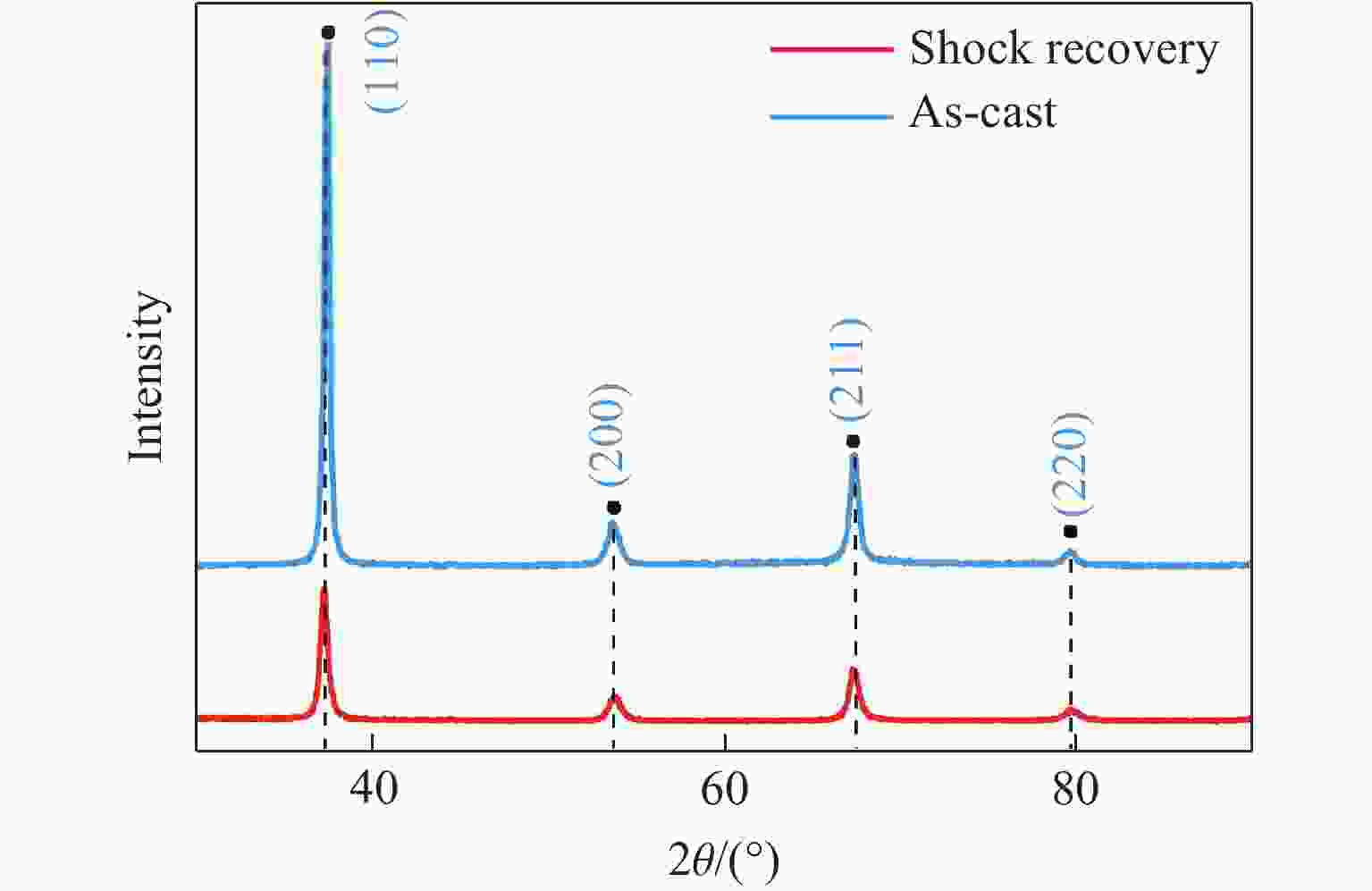
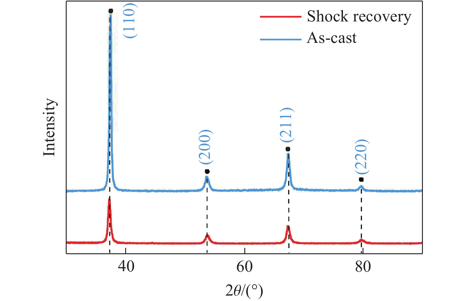
图 7 层裂回收样品(Shot A4)与初始样品的XRD谱比较
Figure 7. Comparison of XRD patterns of recovered and as-cast sample in Shot A4
表 1 不同冲击应力和脉宽加载条件下的层裂实验参数和实验结果
Table 1. Experimental parameters and results for different impact stresses and pulse durations
Shot No. uimp/(m·s−1) σH/GPa Lf/mm Ls/mm τ/μs Δu/(m·s−1) σsp/GPa ${ \dot{\varepsilon }} $/(105 s−1) ar/(107 m·s−2) A1 325 4.64 0.92 1.79 0.19 257.5 3.77 3.11 5.08 A2 400 5.68 0.90 1.82 0.17 262.1 3.84 3.10 11.17 A3 493 7.00 0.91 1.81 0.17 281.0 4.13 3.08 29.92 A4 680 9.34 0.91 1.78 0.20 273.9 4.01 3.32 33.55 B1 487 6.86 0.56 1.80 0.07 328.0 4.80 4.61 59.77 B2 480 6.89 1.15 1.83 0.28 258.5 3.78 2.86 24.02  下载: 导出CSV
-
[1] MIRACLE D B, SENKOV O N. A critical review of high entropy alloys and related concepts [J]. Acta Materialia, 2017, 122: 448–511. doi: 10.1016/j.actamat.2016.08.081 [2] LI W D, XIE D, LI D Y, et al. Mechanical behavior of high-entropy alloys [J]. Progress in Materials Science, 2021, 118: 100777. doi: 10.1016/j.pmatsci.2021.100777 [3] ZHANG Y, ZUO T T, TANG Z, et al. Microstructures and properties of high-entropy alloys [J]. Progress in Materials Science, 2014, 61: 1–93. doi: 10.1016/j.pmatsci.2013.10.001 [4] CHEN X F, WANG Q, CHENG Z Y, et al. Direct observation of chemical short-range order in a medium-entropy alloy [J]. Nature, 2021, 592(7856): 712–716. doi: 10.1038/s41586-021-03428-z [5] JIAN W R, XIE Z C, XU S Z, et al. Effects of lattice distortion and chemical short-range order on the mechanisms of deformation in medium entropy alloy CoCrNi [J]. Acta Materialia, 2020, 199: 352–369. doi: 10.1016/j.actamat.2020.08.044 [6] XUN K H, ZHANG B Z, WANG Q, et al. Local chemical inhomogeneities in TiZrNb-based refractory high-entropy alloys [J]. Journal of Materials Science & Technology, 2023, 135: 221–230. doi: 10.1016/J.JMST.2022.06.047 [7] ZHANG R P, ZHAO S T, DING J, et al. Short-range order and its impact on the CrCoNi medium-entropy alloy [J]. Nature, 2020, 581(7808): 283–287. doi: 10.1038/s41586-020-2275-z [8] LIU D, YU Q, KABRA S, et al. Exceptional fracture toughness of CrCoNi-based medium- and high-entropy alloys at 20 kelvin [J]. Science, 2022, 378(6623): 978–983. doi: 10.1126/science.abp8070 [9] HE J Y, WANG Q, ZHANG H S, et al. Dynamic deformation behavior of a face-centered cubic FeCoNiCrMn high-entropy alloy [J]. Science Bulletin, 2018, 63(6): 362–368. doi: 10.1016/j.scib.2018.01.022 [10] GLUDOVATZ B, HOHENWARTER A, CATOOR D, et al. A fracture-resistant high-entropy alloy for cryogenic applications [J]. Science, 2014, 345(6201): 1153–1158. doi: 10.1126/science.1254581 [11] YE Y X, LIU C Z, WANG H, et al. Friction and wear behavior of a single-phase equiatomic TiZrHfNb high-entropy alloy studied using a nanoscratch technique [J]. Acta Materialia, 2018, 147: 78–89. doi: 10.1016/j.actamat.2018.01.014 [12] SU Z Q, QUAN Z D, SHEN T L, et al. A novel BCC-structure Zr-Nb-Ti medium-entropy alloys (MEAs) with excellent structure and irradiation resistance [J]. Materials, 2022, 15(19): 6565. doi: 10.3390/ma15196565 [13] CANTOR B, CHANG I T H, KNIGHT P, et al. Microstructural development in equiatomic multicomponent alloys [J]. Materials Science and Engineering: A, 2004, 375: 213–218. doi: 10.1016/j.msea.2003.10.257 [14] WU S J, WANG X D, LU J T, et al. Room-temperature mechanical properties of V20Nb20Mo20Ta20W20 high-entropy alloy [J]. Advanced Engineering Materials, 2018, 20(7): 1800028. doi: 10.1002/adem.201800028 [15] HU S W, LI T J, SU Z Q, et al. A novel TiZrNb medium entropy alloy (MEA) with appropriate elastic modulus for biocompatible materials [J]. Materials Science and Engineering: B, 2021, 270: 115226. doi: 10.1016/j.mseb.2021.115226 [16] HU S W, LI T J, LI X, et al. Electrochemical behavior, passive film characterization and in vitro biocompatibility of Ti-Zr-Nb medium-entropy alloys [J]. Journal of Materials Science, 2023, 58(2): 946–960. doi: 10.1007/s10853-022-08128-1 [17] HU S W, LI T J, LI Q L, et al. Microstructure evolution, deformation mechanism, and mechanical properties of biomedical TiZrNb medium entropy alloy processed using equal channel angular pressing [J]. Intermetallics, 2022, 151: 107725. doi: 10.1016/j.intermet.2022.107725 [18] HU S W, LI T J, SU Z Q, et al. Research on suitable strength, elastic modulus and abrasion resistance of Ti-Zr-Nb medium entropy alloys (MEAs) for implant adaptation [J]. Intermetallics, 2022, 140: 107401. doi: 10.1016/j.intermet.2021.107401 [19] ELETI R R, STEPANOV N, YURCHENKO N, et al. Cross-kink unpinning controls the medium- to high-temperature strength of body-centered cubic NbTiZr medium-entropy alloy [J]. Scripta Materialia, 2022, 209: 114367. doi: 10.1016/j.scriptamat.2021.114367 [20] SENKOV O N, RAO S, CHAPUT K J, et al. Compositional effect on microstructure and properties of NbTiZr-based complex concentrated alloys [J]. Acta Materialia, 2018, 151: 201–215. doi: 10.1016/j.actamat.2018.03.065 [21] ZHAO L, ZONG H X, DING X D, et al. Anomalous dislocation core structure in shock compressed bcc high-entropy alloys [J]. Acta Materialia, 2021, 209: 116801. doi: 10.1016/j.actamat.2021.116801 [22] THOMAS S A, HAWKINS M C, MATTHES M K, et al. Dynamic strength properties and alpha-phase shock Hugoniot of iron and steel [J]. Journal of Applied Physics, 2018, 123(17): 175902. doi: 10.1063/1.5019484 [23] CUI Y H, CAI J C, LI Z G, et al. Effect of porosity on dynamic response of additive manufacturing Ti-6Al-4V alloys [J]. Micromachines, 2022, 13(3): 408. doi: 10.3390/mi13030408 [24] JIAO Z Y, LI Z G, WU F C, et al. Phase transition, twinning, and spall damage of NiTi shape memory alloys under shock loading [J]. Materials Science and Engineering: A, 2023, 869: 144775. doi: 10.1016/j.msea.2023.144775 [25] ZHANG Z G, CHEN S, HONG Y F, et al. Multi-scale damage mechanism of hierarchically structured high-strength martensitic steels under shock loading [J]. International Journal of Plasticity, 2024, 175: 103945. doi: 10.1016/j.ijplas.2024.103945 [26] KANEL G I. Spall fracture: methodological aspects, mechanisms and governing factors [J]. International Journal of Fracture, 2010, 163(1/2): 173–191. doi: 10.1007/s10704-009-9438-0 [27] DAVISON L. Spall fracture [M]//Fundamentals of Shock Wave Propagation in Solids. Berlin, Heidelberg: Springer, 2008: 317–342. [28] ANTOUN T, CURRAN D R, RAZORENOV S V, et al. Spall fracture [M]. New York: Springer, 2003. [29] CHEVRIER P, KLEPACZKO J R. Spall fracture: mechanical and microstructural aspects [J]. Engineering Fracture Mechanics, 1999, 63(3): 273–294. doi: 10.1016/S0013-7944(99)00022-3 [30] 周洪强, 张凤国, 潘昊, 等. 材料层裂研究的主要进展 [J]. 高压物理学报, 2019, 33(5): 050301. doi: 10.11858/gywlxb.20180670ZHOU H Q, ZHANG F G, PAN H, et al. Main progress in research on material spalling [J]. Chinese Journal of High Pressure Physics, 2019, 33(5): 050301. doi: 10.11858/gywlxb.20180670 [31] 谭华. 实验冲击波物理 [M]. 北京: 国防工业出版社, 2018: 45−46, 64−65, 269−271.TAN H. Experimental shock wave physics [M]. Beijing: National Defense Industry Press, 2018: 45−46, 64−65, 269−271. [32] 蔡洋, 李超, 卢磊. 冲击载荷下金属材料的微结构-加载特性-层裂响应关系概述 [J]. 高压物理学报, 2021, 35(4): 040104. doi: 10.11858/gywlxb.20200648CAI Y, LI C, LU L. Effects of microstructure and loading characteristics on spallation of metallic materials under shock loading [J]. Chinese Journal of High Pressure Physics, 2021, 35(4): 040104. doi: 10.11858/gywlxb.20200648 [33] LI C, YANG K, TANG X C, et al. Spall strength of a mild carbon steel: effects of tensile stress history and shock-induced microstructure [J]. Materials Science and Engineering: A, 2019, 754: 461–469. doi: 10.1016/j.msea.2019.03.019 [34] GLUZMAN V D, KANEL G I. Measurement of the tensile stresses behind a spalling plane [J]. Journal of Applied Mechanics and Technical Physics, 1984, 24(4): 582–585. doi: 10.1007/BF00907912 [35] ROMANCHENKO V I, STEPANOV G V. Dependence of the critical stresses on the loading time parameters during spall in copper, aluminum, and steel [J]. Journal of Applied Mechanics and Technical Physics, 1980, 21(4): 555–561. doi: 10.1007/BF00916495 [36] ZHANG N B, XU J, FENG Z D, et al. Shock compression and spallation damage of high-entropy alloy Al0.1CoCrFeNi [J]. Journal of Materials Science & Technology, 2022, 128: 1–9. doi: 10.1016/j.jmst.2022.02.056 [37] CUI A R, HU S C, ZHANG S, et al. Spall response of medium-entropy alloy CrCoNi under plate impact [J]. International Journal of Mechanical Sciences, 2023, 252: 108331. doi: 10.1016/j.ijmecsci.2023.108331 [38] CHENG J C, QIN H L, LI C, et al. Deformation and damage of equiatomic CoCrFeNi high-entropy alloy under plate impact loading [J]. Materials Science and Engineering: A, 2023, 862: 144432. doi: 10.1016/j.msea.2022.144432 [39] ZHANG N B, TANG Z J, LIN Z H, et al. Deformation and damage of heterogeneous-structured high-entropy alloy CrMnFeCoNi under plate impact [J]. Materials Science and Engineering: A, 2022, 843: 143069. doi: 10.1016/j.msea.2022.143069 [40] QI M L, BIE B X, ZHAO F P, et al. A metallography and X-ray tomography study of spall damage in ultrapure Al [J]. AIP Advances, 2014, 4(7): 077118. doi: 10.1063/1.4890310 -

 下载:
下载:

计量
- 文章访问数: 637
- HTML全文浏览量: 269
- PDF下载量: 56
