


Mechanical Properties and Energy Evolution Characteristics of Fracture-Bearing Rocks under Uniaxial Compression
-
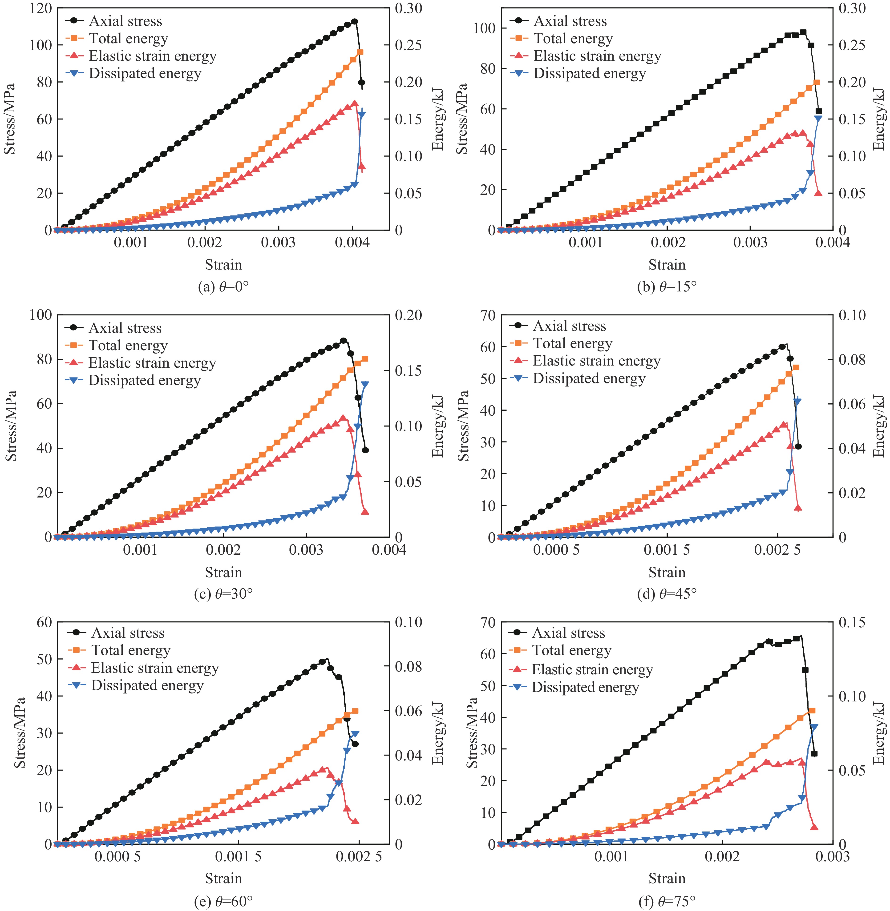
摘要: 为了研究裂隙倾角对岩石力学性能以及破坏过程中能量演化机制的影响,基于颗粒流离散元数值平台,构建了具有不同裂隙倾角的岩石的计算模型,开展了含不同裂隙倾角岩石的单轴压缩数值试验研究。结果表明:随着裂隙倾角的增大,裂隙岩石的峰值强度和弹性模量均呈先减小后增大的“V”形变化趋势;当裂隙倾角较小时,岩石试样主要发生剪切破坏和竖向劈裂破坏,拉剪裂纹数主要呈台阶式增长;裂隙倾角越大,岩石破坏模式将过渡为竖向劈裂和剪切的混合破坏,拉剪裂纹数变化曲线呈指数增长;随着裂隙倾角的增大,岩石试样的总输入能量和弹性应变能呈先减小后增大的变化趋势;裂隙角度越大,耗散能上升越快,但试样破坏时的最终耗散能则越低。裂隙结构的存在对试样在受压破坏时的储能极限均有明显的弱化作用,削弱了岩石吸收和储存弹性应变能的能力,增强了其在峰值应力处的能量耗散能力。Abstract: To study the influence of crack inclination angle on the mechanical properties and the energy evolution mechanism during the rock failure, a calculation model was constructed based on the particle flow dispersion element numerical platform, and uniaxial compression numerical experiments were conducted on rock samples with different crack inclination angles. The research results indicate that as the crack inclination angle increases, the peak strength and elastic modulus of fractured rocks show a “V” shaped trend of first decreasing and then increasing. When the crack inclination angle is small, the rock sample mainly undergoes shear failure and vertical splitting failure, and the number of tensile and shear cracks mainly increases in a stepped pattern. The larger the crack inclination angle, the more the rock failure mode will transition to a mixture of vertical splitting and shear failure, and the curve of the number of tensile and shear cracks will increase exponentially. As the crack inclination angle increases, the total input energy and elastic strain energy of the rock sample show a trend of first decreasing and then increasing. The larger the crack inclination angle, the faster the increase in dissipated energy, but the lower the final dissipated energy when the rock sample fails. The existence of cracks significantly weakens the energy storage limit, weakens the ability of the rock to absorb and store elastic strain energy, and enhances its energy dissipation ability at peak stress in the rock specimen during compressive failure.
-
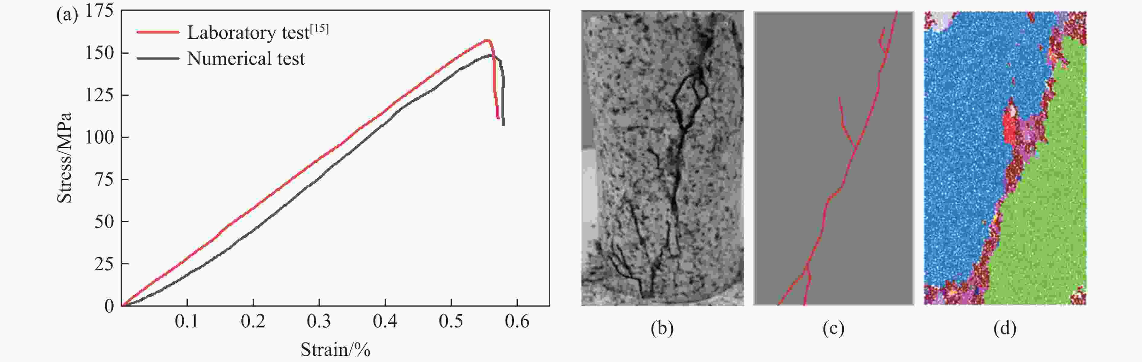
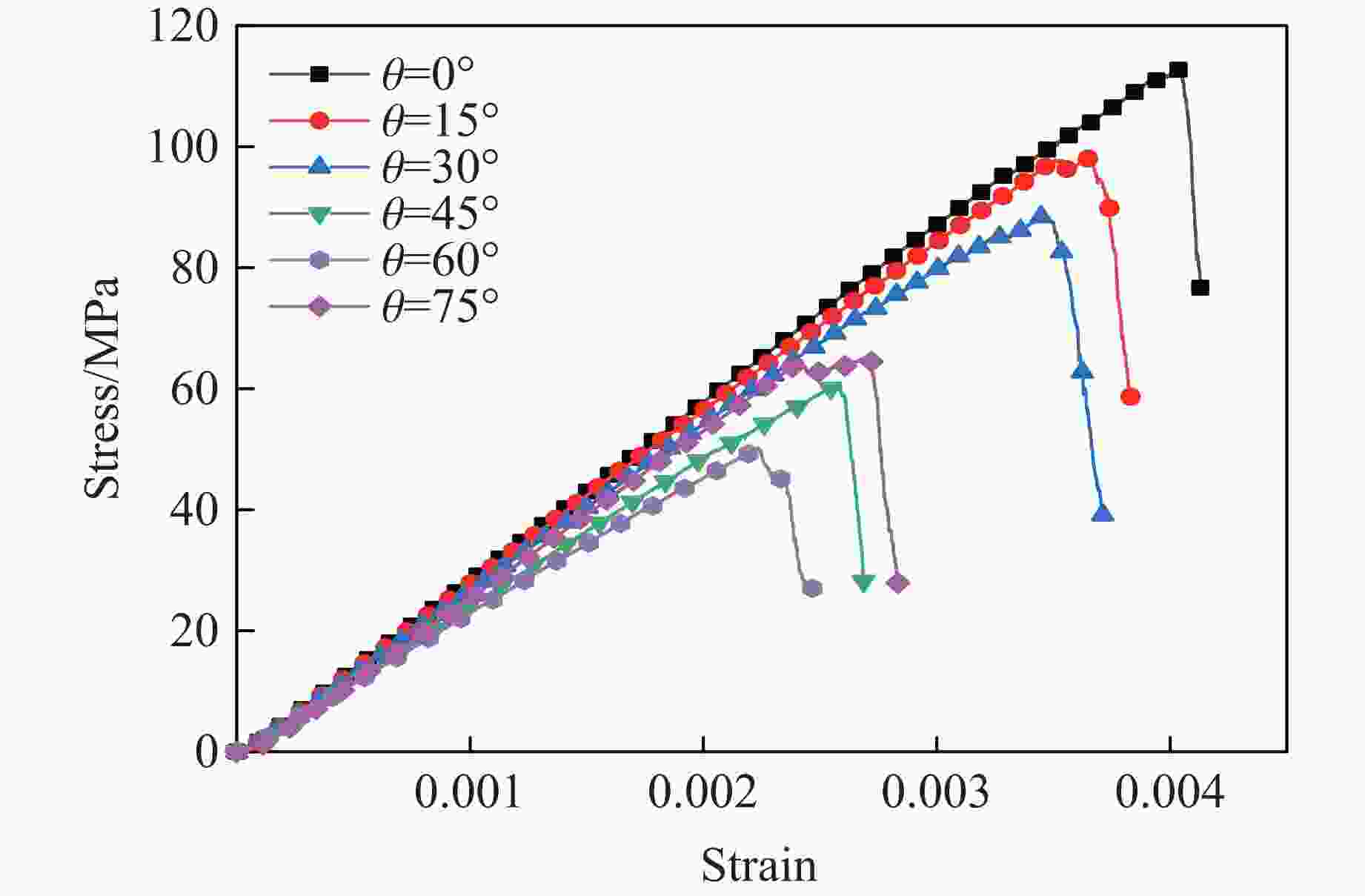
图 3 不同裂隙倾角岩石试样的应力-应变关系
Figure 3. Stress-strain relationship of rock samples with different crack inclination angles
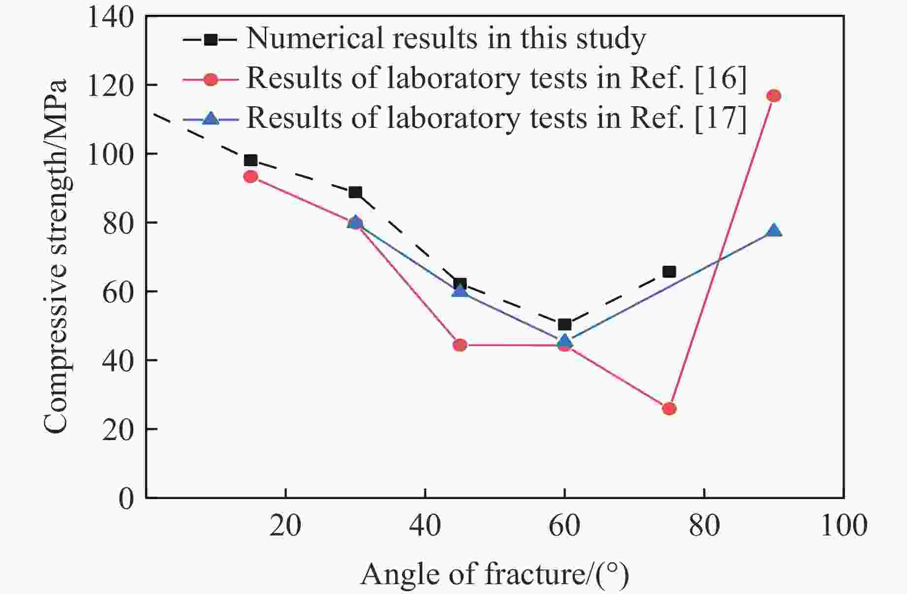
图 4 抗压强度与裂隙角度关系曲线
Figure 4. Relationship curve between compressive strength and crack inclination angle
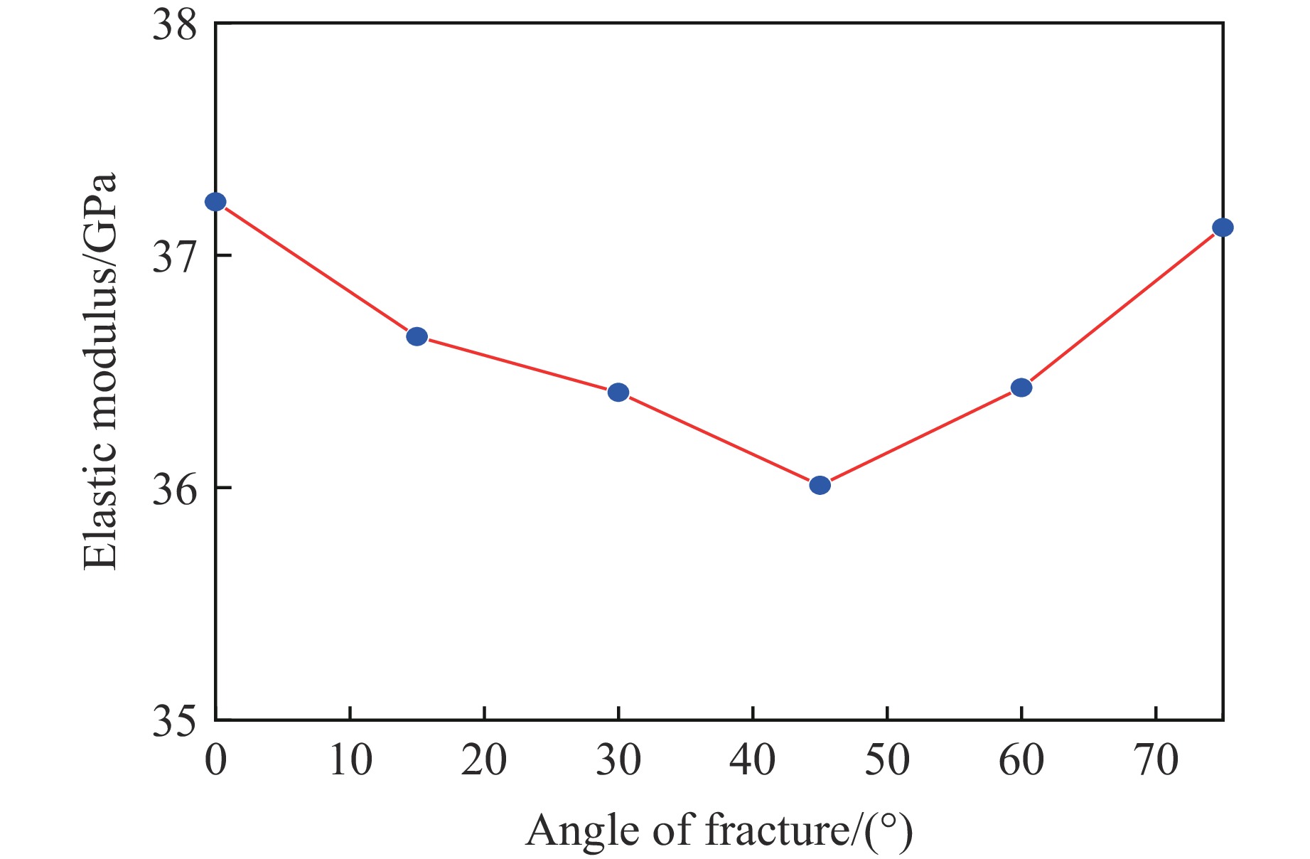
图 5 弹性模量与裂隙角度关系曲线
Figure 5. Relationship curve between elastic modulus and crack inclination angle
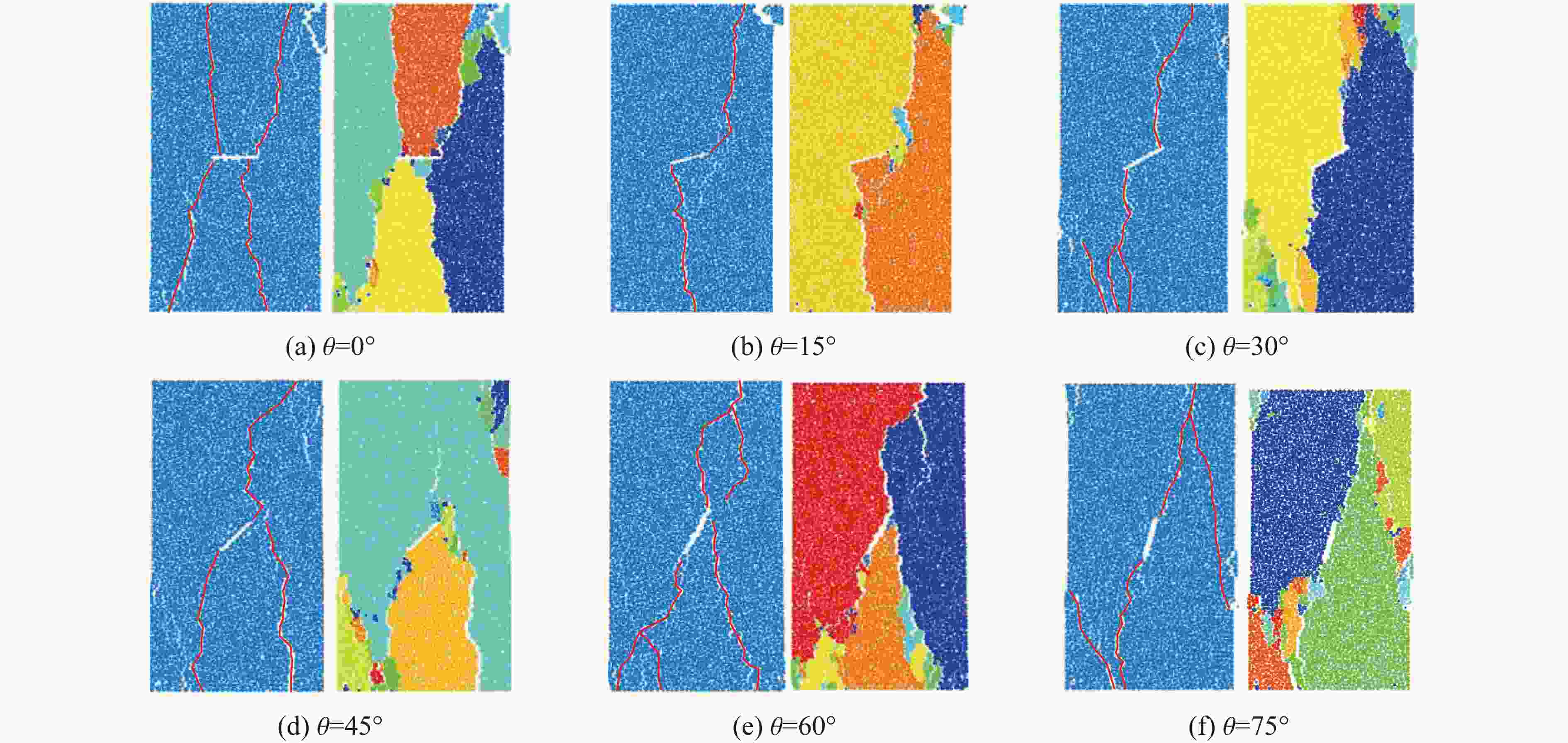
图 6 不同裂隙倾角岩样的典型破坏特征
Figure 6. Typical failure characteristics of rock samples with different crack inclination angles
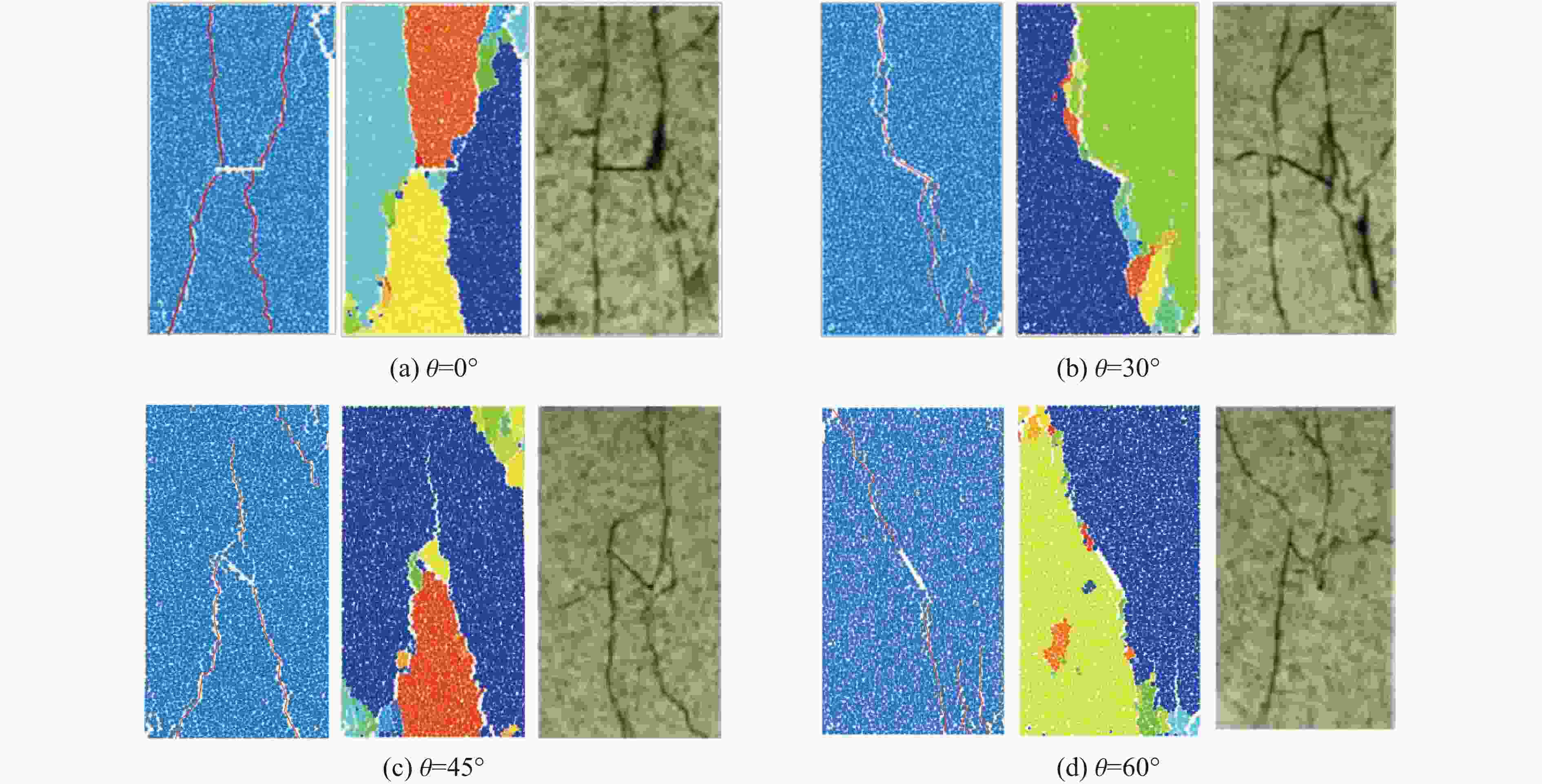
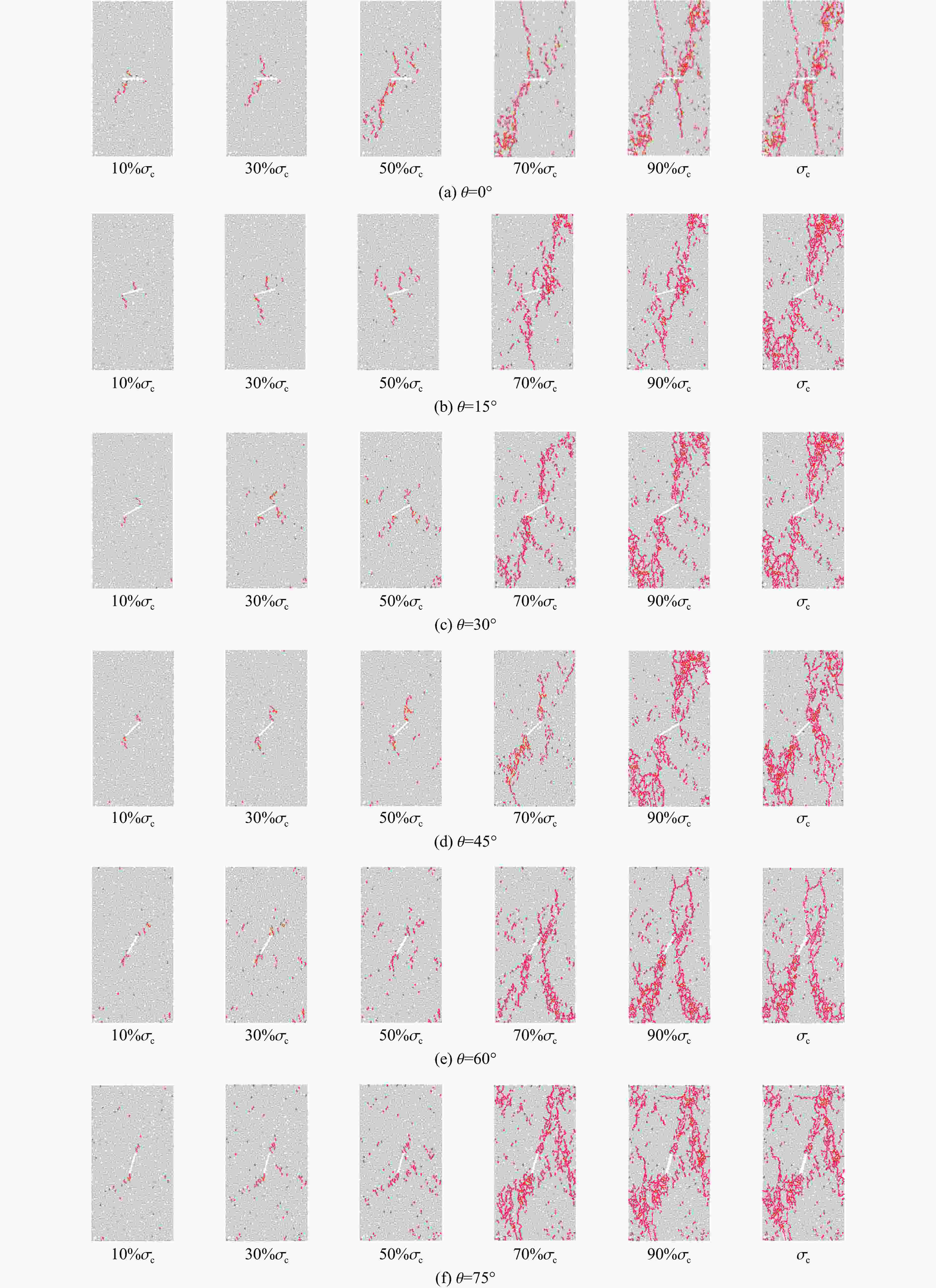
图 9 裂隙岩石内微裂纹的演化特征
Figure 9. Evolution characteristics of microcracks in fractured rocks
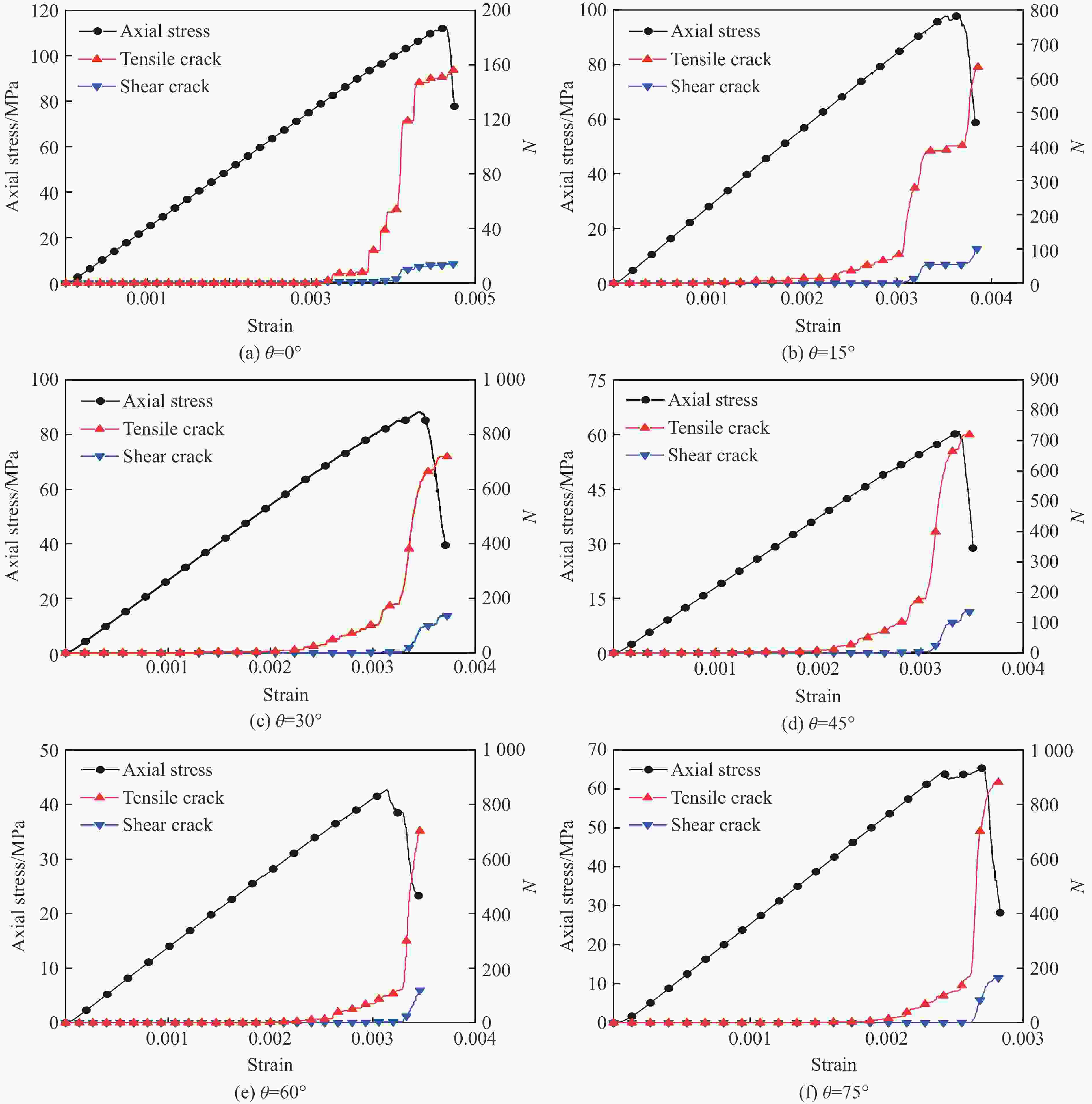
图 10 不同裂隙倾角岩石试样的拉剪裂纹演化规律
Figure 10. Evolution law of tensile and shear cracks in rock samples with different crack inclination angles
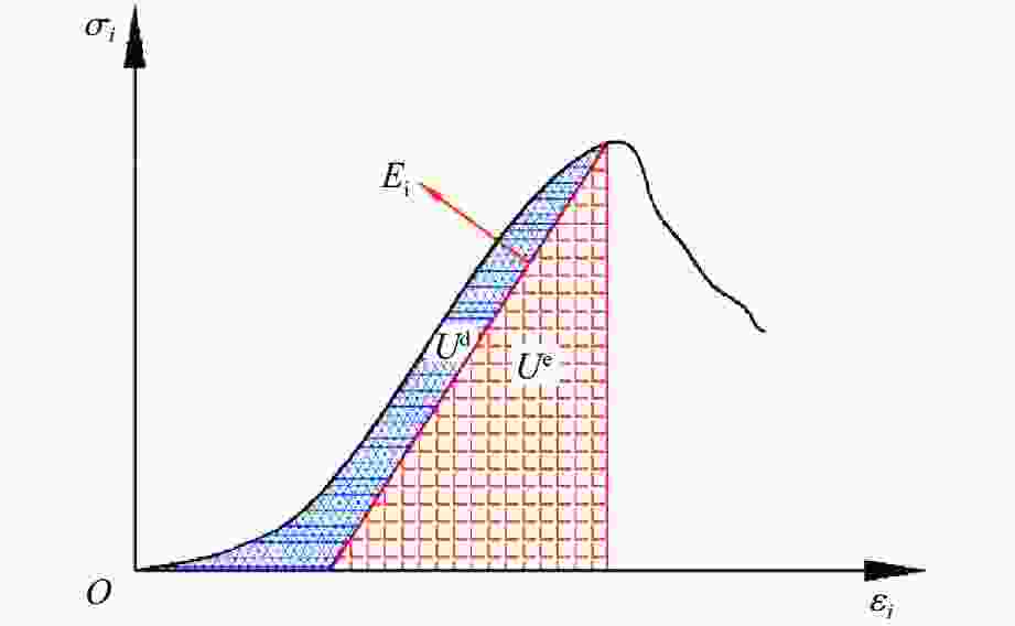
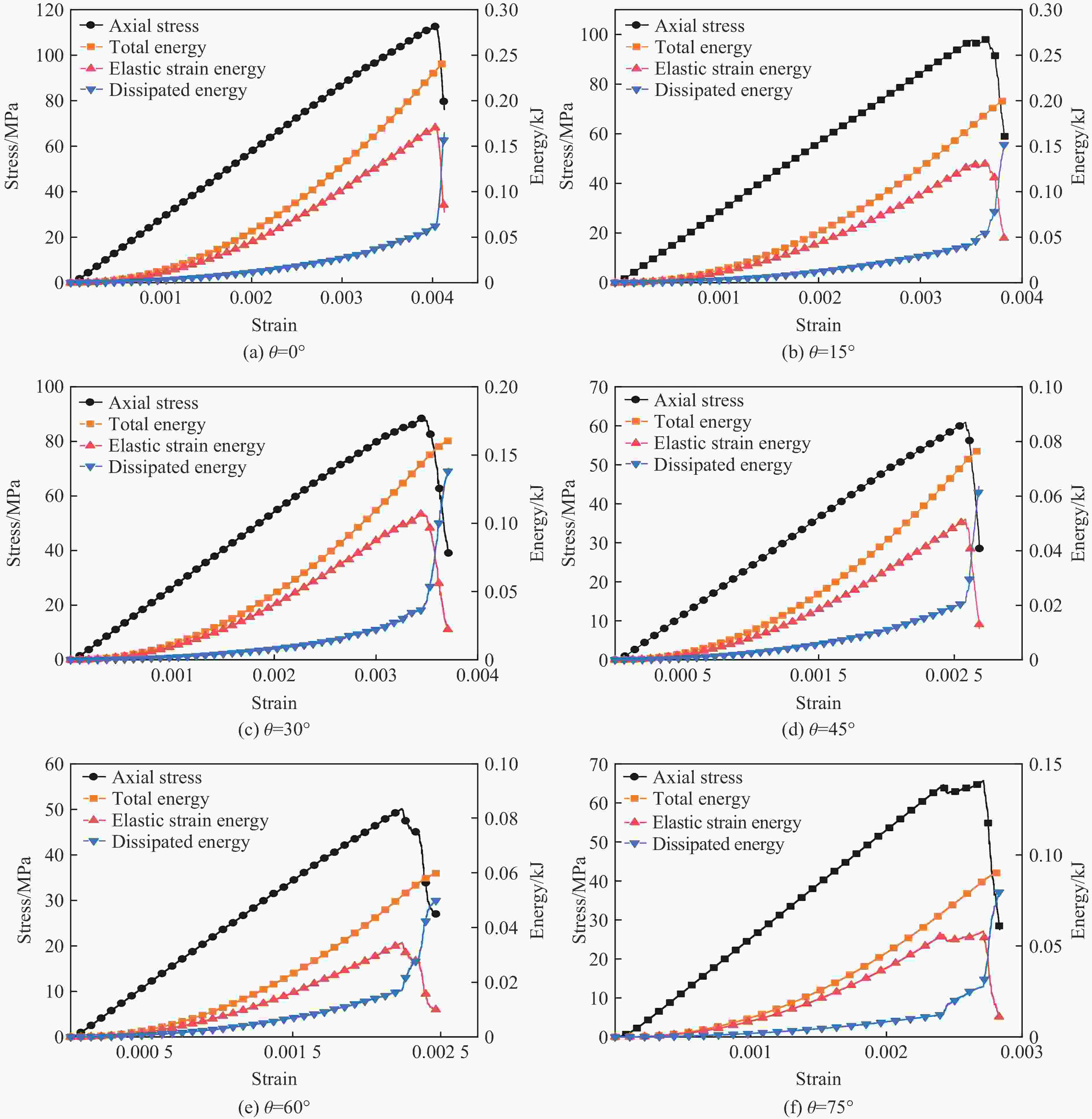
图 12 不同裂隙倾角岩石试样的能量演化特征
Figure 12. Energy evolution characteristics of rock samples with different crack inclination angles
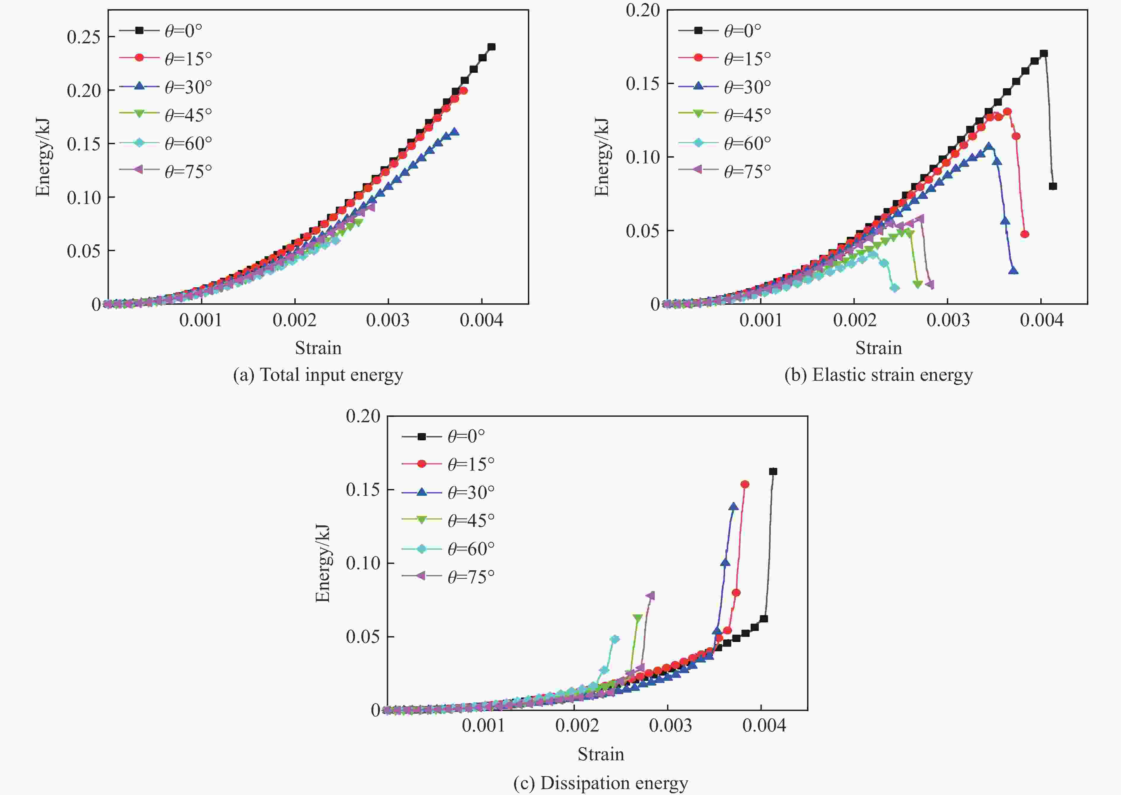
图 13 裂隙倾角对能量演化特征影响
Figure 13. Effect of crack inclination angle on energy evolution characteristics
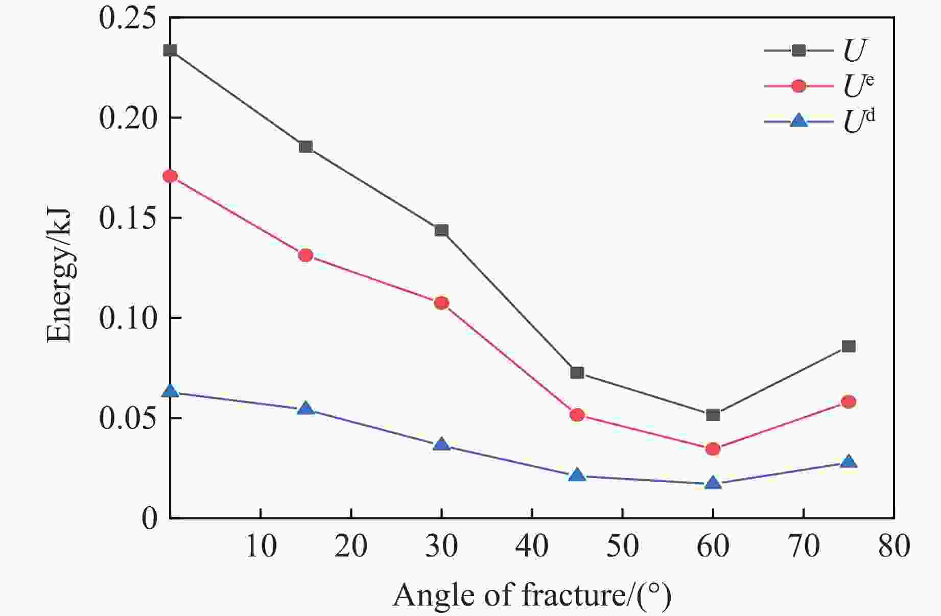
图 14 不同裂隙倾角岩石试样在峰值应力处的能量演化特征
Figure 14. Energy evolution characteristics of rock samples with different crack inclination angles at peak stress
表 1 岩石的宏观力学参数
Table 1. Macromechanical parameters of rocks
Material Rock density/
(g·cm−3)Compressive
strength/MPaTensile
strength/MPaElastic
modulus/GPaPoisson’s
ratioCohesive
force/MPaFriction
angle/(°)Rock materials[15] 2.63 155.1 11.06 37.63 0.21 Structural plane 0.5 70  下载: 导出CSV
表 2 岩石的细观参数
Table 2. Mesoscopic parameters of rocks
Effective modulus
of parallel
bonding/GPaStiffness
ratioLinear contact
effective
modulus/GPaTangential bonding
strength/MPaNormal bonding
strength/MPaFriction
angle/(°)Frictional
coefficient98.6 1.5 29.2 28 7.6 70 0.5
下载: 导出CSV
-
[1] 佘诗刚, 林鹏. 中国岩石工程若干进展与挑战 [J]. 岩石力学与工程学报, 2014, 33(3): 433–457. doi: 10.13722/j.cnki.jrme.2014.03.001SHE S G, LIN P. Some developments and challenging issues in rock engineering field in China [J]. Chinese Journal of Rock Mechanics and Engineering, 2014, 33(3): 433–457. doi: 10.13722/j.cnki.jrme.2014.03.001 [2] LI Y P, CHEN L Z, WANG Y H. Experimental research on pre-cracked marble under compression [J]. International Journal of Solids and Structures, 2005, 42(9/10): 2505–2516. doi: 10.1016/j.ijsolstr.2004.09.033 [3] WANG S Y, SLOAN S W, SHENG D C, et al. Numerical study of failure behavior of pre-cracked rock specimens under conventional triaxial compression [J]. International Journal of Solids and Structures, 2014, 51(5): 1132–1148. doi: 10.1016/j.ijsolstr.2013.12.012 [4] 陈卫忠, 杨建平, 邹喜德, 等. 裂隙岩体宏观力学参数研究 [J]. 岩石力学与工程学报, 2008, 27(8): 1569–1575.CHEN W Z, YANG J P, ZOU X D, et al. Research on micromechanical parameters of fractured rock mass [J]. Chinese Journal of Rock Mechanics and Engineering, 2008, 27(8): 1569–1575. [5] 易婷, 唐建新, 王艳磊. 裂隙倾角及数目对岩体强度和破坏模式的影响 [J]. 地下空间与工程学报, 2021, 17(1): 98–106, 134.YI T, TANG J X, WANG Y L. The influence of the inclination and number of cracks on the strength and failure mode of rock mass [J]. Chinese Journal of Underground Space and Engineering, 2021, 17(1): 98–106, 134. [6] 朱泽奇, 肖培伟, 盛谦, 等. 基于数字图像处理的非均质岩石材料破坏过程模拟 [J]. 岩土力学, 2011, 32(12): 3780–3786. doi: 10.3969/j.issn.1000-7598.2011.12.040ZHU Z Q, XIAO P W, SHENG Q, et al. Numerical simulation of fracture propagation of heterogeneous rock material based on digital image processing [J]. Rock and Soil Mechanics, 2011, 32(12): 3780–3786. doi: 10.3969/j.issn.1000-7598.2011.12.040 [7] 张仕林, 杜贻腾, 李延春, 等. 单轴压缩荷载下红砂岩不同张开度三维通透裂隙扩展机理研究 [J]. 西安科技大学学报, 2016, 36(4): 548–553. doi: 10.13800/j.cnki.xakjdxxb.2016.0415ZHANG S L, DU Y T, LI Y C, et al. Propagation mechanism of 3D through fracture with under uniaxial load [J]. Journal of Xi’an University of Science and Technology, 2016, 36(4): 548–553. doi: 10.13800/j.cnki.xakjdxxb.2016.0415 [8] 唐春安, 刘红元, 秦四清, 等. 非均质性对岩石介质中裂纹扩展模式的影响 [J]. 地球物理学报, 2000, 43(1): 116–121.TANG C A, LIU H Y, QIN S Q, et al. Influence of heterogeneity on crack propagation modes in brittle rock [J]. Chinese Journal of Geophysics, 2000, 43(1): 116–121. [9] 谢和平, 鞠杨, 黎立云. 基于能量耗散与释放原理的岩石强度与整体破坏准则 [J]. 岩石力学与工程学报, 2005, 24(17): 3003–3010. doi: 10.3321/j.issn:1000-6915.2005.17.001XIE H P, JU Y, LI L Y. Rock strength and global failure criteria based on the principle of energy dissipation and release [J]. Chinese Journal of Rock Mechanics and Engineering, 2005, 24(17): 3003–3010. doi: 10.3321/j.issn:1000-6915.2005.17.001 [10] 谢和平, 鞠杨, 黎立云, 等. 岩体变形破坏过程的能量机制 [J]. 岩石力学与工程学报, 2008, 27(9): 1729–1740.XIE H P, JU Y, LI L Y, et al. Energy mechanism of rock deformation and failure process [J]. Chinese Journal of Rock Mechanics and Engineering, 2008, 27(9): 1729–1740. [11] 武晋文, 赵阳升, 万志军, 等. 高温均匀压力花岗岩热破裂声发射特性实验研究 [J]. 煤炭学报, 2012, 37(7): 1111–1117. doi: 10.13225/j.cnki.jccs.2012.07.016WU J W, ZHAO Y S, WAN Z J, et al. Experimental study of acoustic emission of granite due to thermal cracking under high temperature and isostatic stress [J]. Journal of China Coal Society, 2012, 37(7): 1111–1117. doi: 10.13225/j.cnki.jccs.2012.07.016 [12] 孙友杰, 戚承志, 朱华挺, 等. 岩石动态断裂过程的能量分析 [J]. 地下空间与工程学报, 2020, 16(1): 43–49.SUN Y J, QI C Z, ZHU H T, et al. Energy analysis of rock dynamic fracture process [J]. Chinese Journal of Underground Space and Engineering, 2020, 16(1): 43–49. [13] POTYONDY D O, CUNDALL P A. A bonded-particle model for rock [J]. International Journal of Rock Mechanics & Mining Sciences, 2004, 41(8): 1329–1364. [14] 耿萍, 卢志楷, 丁梯. 基于颗粒流的围岩注浆动态过程模拟研究 [J]. 铁道工程学报, 2017, 34(3): 34–40. doi: 10.3969/j.issn.1006-2106.2017.03.007GENG P, LU Z K, DING T. Research on the dynamic process simulation of rock grouting based on particle Flow [J]. Journal of Railway Engineering Society, 2017, 34(3): 34–40. doi: 10.3969/j.issn.1006-2106.2017.03.007 [15] 王春萍, 王璐, 刘建锋, 等. 单轴压缩条件下单裂隙花岗岩力学特性及破坏特征 [J/OL]. 西南交通大学学报 (2023-07-10)[2024-01-18]. http://kns.cnki.net/kcms/detail/51.1277.u.20230706.1836.007.html.WANG C P, WANG L, LIU J F, et al. Investigations on the mechanical behavior and failure mechanism of single fractured granite under uniaxial compression [J/OL]. Journal of Southwest Jiaotong University (2023-07-10)[2024-01-18]. http://kns.cnki.net/kcms/detail/51.1277.u.20230706.1836.007.html. [16] 郭奇峰, 武旭, 蔡美峰, 等. 预制裂隙花岗岩的强度特征与破坏模式试验 [J]. 工程科学学报, 2019, 41(1): 43–52.GUO Q F, WU X, CAI M F, et al. Experiment on the strength characteristics and failure modes of granite with pre-existing cracks [J]. Chinese Journal of Engineering, 2019, 41(1): 43−52. [17] 郭奇峰, 武旭, 蔡美峰, 等. 预制裂隙花岗岩的裂纹起裂机理试验研究 [J]. 煤炭学报, 2019, 44(Suppl 2): 476–483. doi: 10.13225/j.cnki.jccs.2019.1212GUO Q F, WU X, CAI M F, et al. Crack initiation mechanism of pre-existing cracked granite [J]. Journal of China Coal Society, 2019, 44(Suppl 2): 476–483. doi: 10.13225/j.cnki.jccs.2019.1212 [18] 蒋明镜, 张宁, 申志福, 等. 含裂隙岩体单轴压缩裂纹扩展机制离散元分析 [J]. 岩土力学, 2015, 36(11): 3293–3300. doi: 10.16285/j.rsm.2015.11.034JIANG M J, ZHANG N, SHEN Z F, et al. DEM analyses of crack propagation in flawed rock mass under uniaxial compression [J]. Rock and Soil Mechanics, 2015, 36(11): 3293–3300. doi: 10.16285/j.rsm.2015.11.034 [19] BROBERG K B. Cracks and fracture [M]. New York, NY: Academic Press, 1999. [20] WANG Q S, CHEN J X, GUO J Q, et al. Acoustic emission characteristics and energy mechanism in karst limestone failure under uniaxial and triaxle compression [J]. Bulletin of Engineering Geology & the Environment, 2019, 78: 1427–1442. [21] NING J, WANG J, JIANG J Q, et al. Estimation of crack initiation and propagation thresholds of confined brittle coal specimens based on energy dissipation theory [J]. Rock Mechanics & Rock Engineering. 2018, 51: 119–134. [22] 黄达, 黄润秋, 张永兴. 粗晶大理岩单轴压缩力学特性的静态加载速率效应及能量机制试验研究 [J]. 岩石力学与工程学报, 2012, 31(2): 245–255. doi: 10.3969/j.issn.1000-6915.2012.02.003HUANG D, HUANG R Q, ZHANG Y X. Experimental investigations on static loading rate effects on mechanical properties and energy mechanism of coarse crystal grain marble under uniaxial compression [J]. Chinese Journal of Rock Mechanics and Engineering, 2012, 31(2): 245–255. doi: 10.3969/j.issn.1000-6915.2012.02.003 -

 下载:
下载:


计量
- 文章访问数: 942
- HTML全文浏览量: 414
- PDF下载量: 58
