


Optimization and Experimental Study of Pre-Splitting Blasting Parameters in a Certain Open-Pit Mine
-
摘要: 为了得到确保露天矿山边坡安全稳定的最佳预裂爆破参数组合,采用数值模拟结合相似模型试验的方法,探讨了岩石双孔爆破下裂纹扩展规律,并进行了现场预裂爆破试验。结果表明:裂纹先由炮孔壁产生,且炮孔附近的原岩破坏程度较大;随着不耦合系数由1.33增大至3.00,孔壁所承受的冲击压力显著减小,粉碎区半径逐渐减小。采用极差分析法,研究了不同因素对试验指标的影响程度,根据评价指标确定试验因素的最优组合。模型试验结果表明:孔距与孔径之比为9、不耦合系数为3.00、起爆延期时间为12 ms、最大单响药量为5.4 g(三孔一响)的组合条件下,模型试件预裂成缝效果最佳。根据数值模拟及相似模型试验结果,结合理论计算,选取孔距为0.8 m(孔距与孔径之比约为9)、不耦合系数为3.00、延期时间为12 ms、最大单响药量为11.25 kg(三孔一响)的预裂爆破参数进行现场试验,取得了良好的预裂效果。研究结果可以为露天矿山现场预裂爆破参数的设计提供参考,对于实现精确控制爆破、确保露天矿山边坡安全稳定具有重要意义。Abstract: In order to obtain the optimal combination of pre-splitting blasting parameters to ensure the safety and stability of open-pit mine slope, the law of crack propagation under rock double-hole blasting was discussed by numerical simulation combined with similar model experiment, and the field pre-splitting blasting experiment was carried out. The results show that the cracks are first generated by the blasthole wall and the original rock near the blasthole is more damaged. As the decoupling coefficient increases from 1.33 to 3.00, the impact pressure on the hole wall decreases significantly, and the radius of the crushing zone decreases gradually. The range analysis method was used to study the influence of different factors on the experiment index, and the optimal combination of experiment factors was determined according to the evaluation index. The results of the model experiment indicate that the pre-splitting effect of the model specimen is the best under the combined conditions of the hole spacing-to-aperture ratio of 9, the decoupling coefficient of 3.00, the initiation delay time of 12 ms, and the maximum charge weight per delayed interval of 5.4 g (three holes and one shot). According to the results of numerical simulation and similar model experiment, combined with theoretical calculation, the pre-splitting blasting parameters with hole spacing of 0.8 m (the spacing-to-aperture ratio of about 9), decoupling coefficient of 3.00, delay time of 12 ms and maximum charge weight per delayed interval of 11.25 kg (three holes and one shot) were selected for field experiment, and good pre-splitting effect was achieved. The research results can provide reference for the design of pre-splitting blasting parameters in open-pit mines, and it is of great significance to realize accurate control blasting and ensure the safety and stability of open-pit mine slopes.
-
图 4 双孔连线中点处最大拉应力随孔距的变化曲线
Figure 4. Change curves of the maximum tensile stress at the midpoint of double hole line
图 5 L=81 cm时不同不耦合系数条件下的孔壁压力时程曲线
Figure 5. Time-history curves of the hole wall pressure under different decoupling coefficients at L=81 cm
图 6 L=81 cm时粉碎区半径随不耦合系数的变化曲线
Figure 6. Change curve of the radius of the crushing zone with decoupling coefficient at L=81 cm
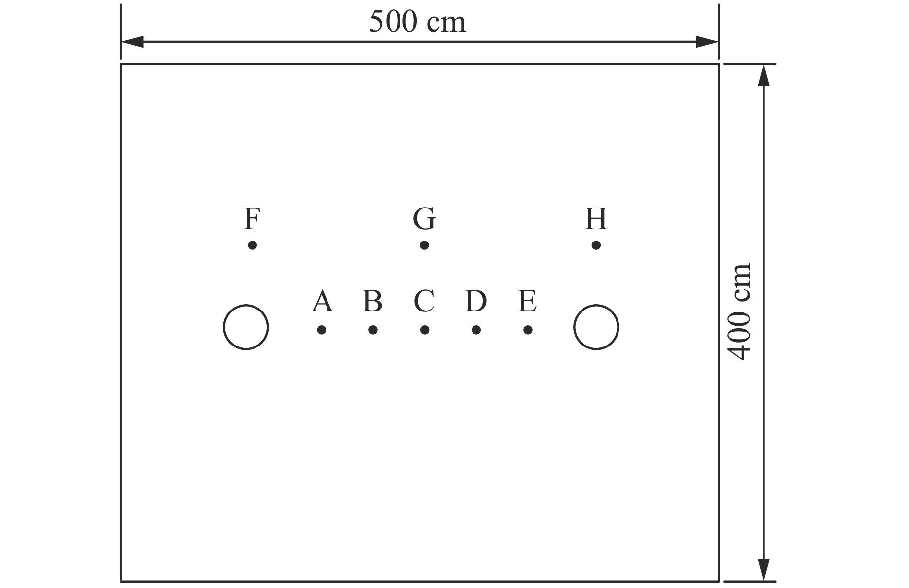
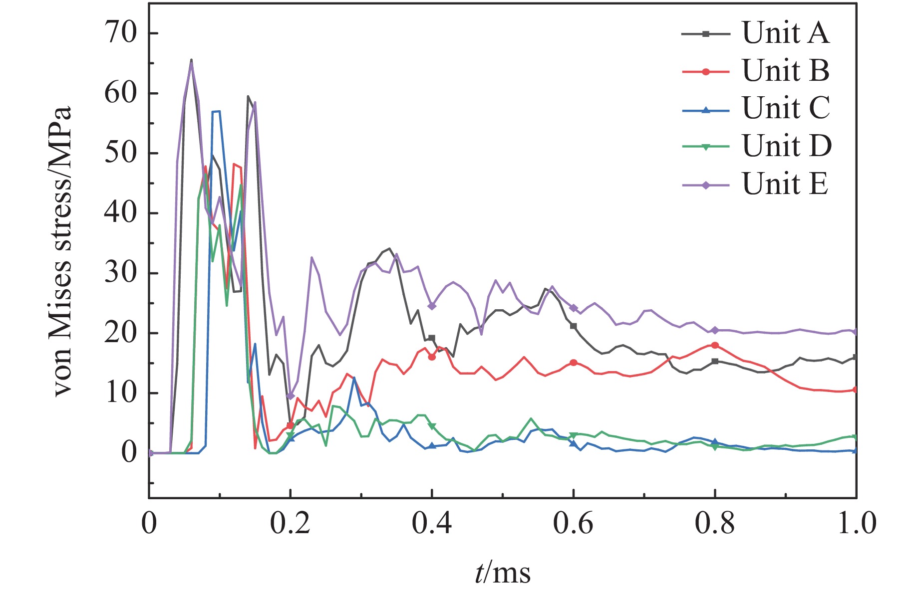
图 9 同时起爆时5个单元的有效应力变化曲线
Figure 9. von Mises stress variation curves of five units during simultaneous detonation
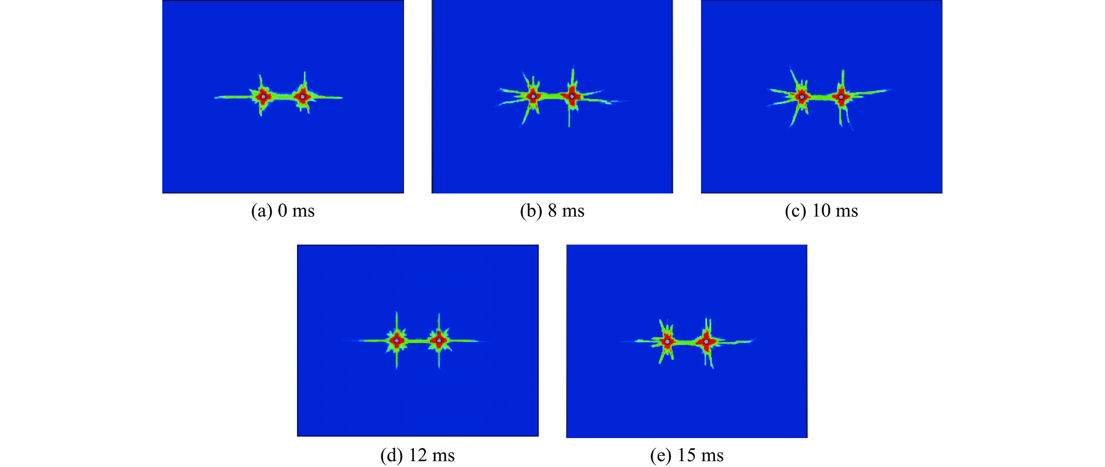
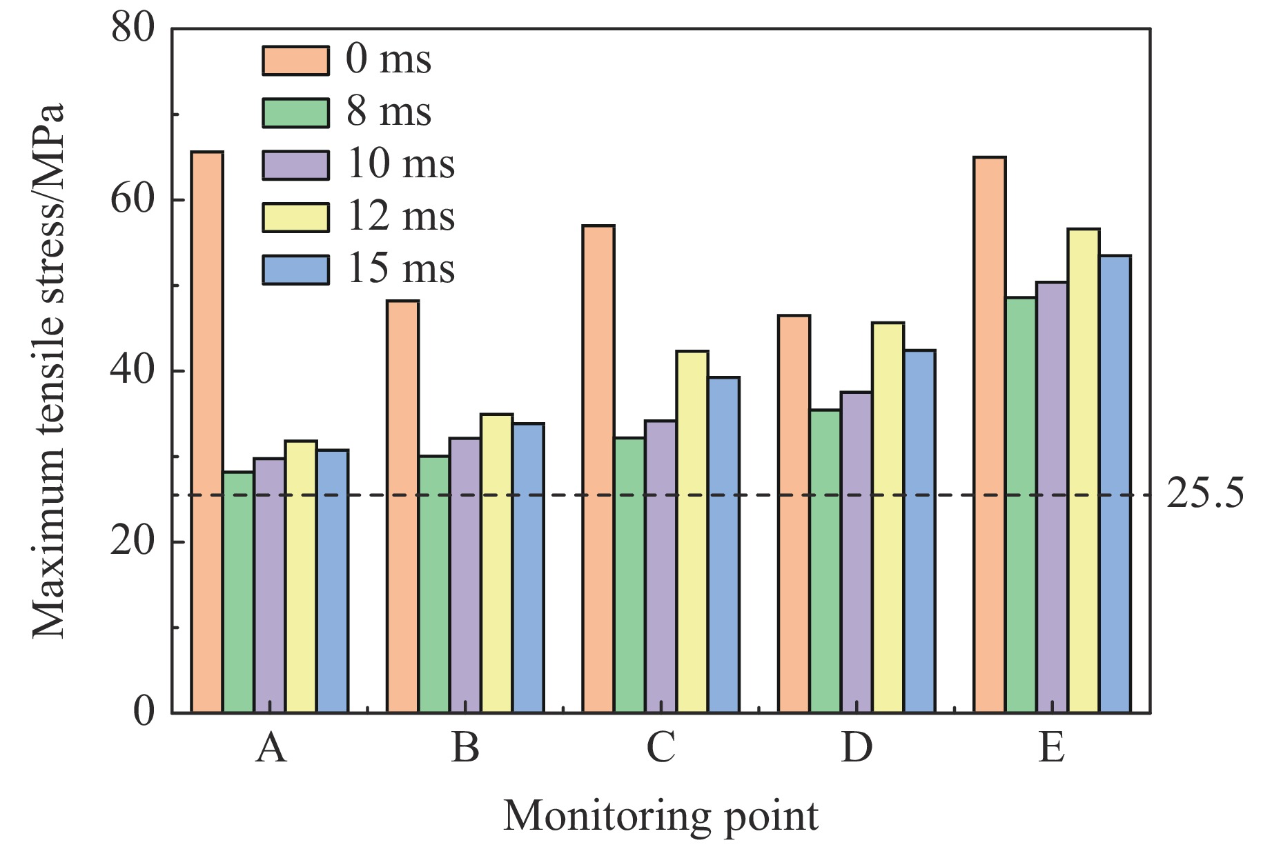
图 10 破坏岩体单元最大拉应力随延期时间的变化
Figure 10. Variations of the maximum tensile stress of the failure rock mass unit with the delay time
图 11 保留岩体单元最大拉应力随延期时间的变化
Figure 11. Variations of the maximum tensile stress of retaining rock mass unit with delay time
表 1 大理岩参数
Table 1. Marble parameters
ρ/(kg·m−3) E/GPa ν σbc/MPa Rm/MPa G/GPa K/GPa Cρρr/(kg·m−2·s−1) 2700 55.8 0.31 74.7 8.5 22.3 37.2 3.6×10⁶  下载: 导出CSV
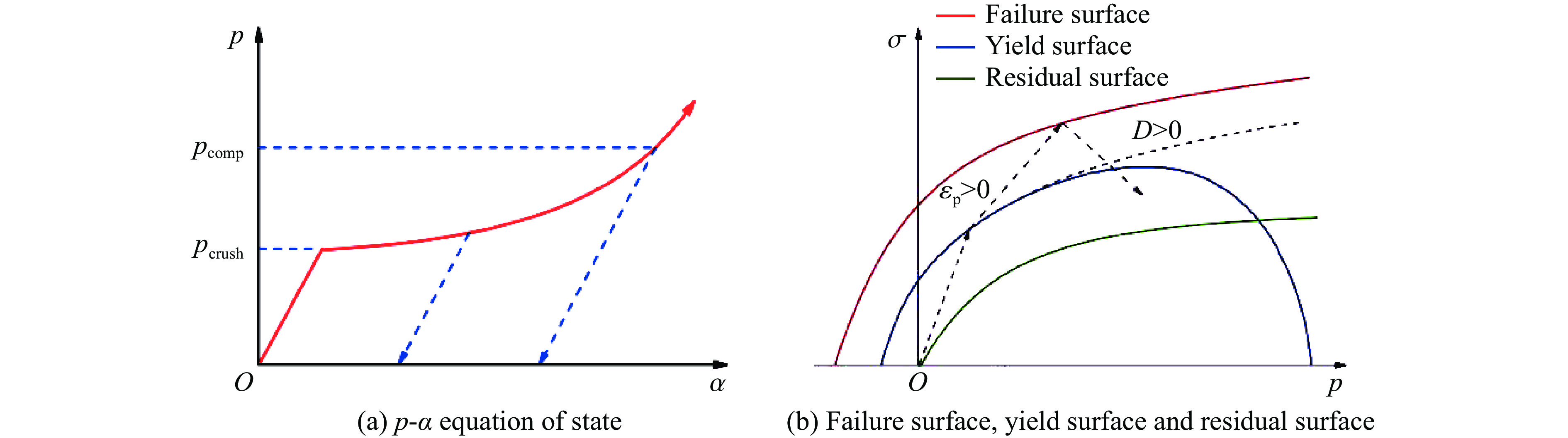
表 2 岩石RHT模型参数
Table 2. Rock RHT model parameters
fc/GPa N α0 pel/GPa βc βt A1/GPa A2/GPa A3/GPa B0 B1 0.1678 4.00 1.0 0.016 0.0244 0.0294 45.39 40.85 41.98 0.9 0.9 T1/GPa T2/GPa ${\dot{\varepsilon}}_{0}^{\text{c} }/{\text{s} }^{ {-1} }$ ${\dot{\varepsilon}}_{0}^{\text{t} }/{\text{s} }^{ {-1} }$ ${\dot{\varepsilon}}^{\text{c} }/{\text{s} }^{ {-1} }$ ${\dot{\varepsilon}}^{\text{t} }/{\text{s} }^{ {-1} }$ D1 D2 B $\mathit{{g} }_{\text{t} }^{\text{*} }$ ${{g}}_{\text{c}}^{\text{*}} $ 45.39 0 3.0×10⁻⁵ 3.0×10⁻⁶ 3.0×1025 3.0×1025 0.037 1.0 0.0105 0.7 0.78 A n ${{f}}_{\text{s}}^{\text{*}} $ ${{f}}_{\text{t}}^{\text{*}} $ Q0 ζ ${{ \varepsilon }}_{\text{p}}^{\text{m}} $ Af nf pcomp/MPa 2.51 0.72 0.21 0.04 0.68 0.5 0.015 0.25 0.62 8.00
下载: 导出CSV
表 3 炸药材料及JWL状态方程参数
Table 3. Explosive material and the JWL equation of state parameters
ρb/(kg·m−3) Cd/(m·s−1) Ae/GPa Be/GPa R1 R2 $\omega $ 1100 4500 625.3 23.29 5.25 1.6 0.28
下载: 导出CSV
表 4 模型材料指标
Table 4. Model material indicators
ρm/(kg·m−3) σm/MPa Em/GPa Cρρr/(kg·m−2·s−1) 2680 30.02 28.1 5.06×10⁶
下载: 导出CSV
表 5 量纲分析
Table 5. Dimensional analysis
ρ σbc E Cρρr H Cd ρb FL−4T2 FL−2 FL−2 FL−3T L LT−1 FL−4T2
下载: 导出CSV
表 6 正交试验方案设计
Table 6. Orthogonal experimental scheme design
Test No. k Δt/ms Q/g Error term Test No. k Δt/ms Q/g Error term 1 1.33 8 1.8 1 9 2.00 8 5.4 2 2 1.33 10 3.6 2 10 2.00 10 1.8* 1 3 1.33 12 5.4 3 11 2.00 12 1.8 4 4 1.33 15 1.8* 4 12 2.00 15 3.6 3 5 1.67 8 3.6 4 13 3.00 8 1.8* 3 6 1.67 10 1.8 3 14 3.00 10 5.4 4 7 1.67 12 1.8* 2 15 3.00 12 3.6 1 8 1.67 15 5.4 1 16 3.00 15 1.8 2
下载: 导出CSV
表 7 爆破效果统计
Table 7. Statistics of blasting effects
Test No. Evaluating indicator Test No. Evaluating indicator δ/% b/mm δ/% b/mm 1 45 51 9 65 16 2 48 63 10 76 15 3 51 80 11 70 10 4 41 54 12 65 12 5 56 41 13 76 12 6 30 45 14 90 21 7 78 62 15 87 17 8 62 51 16 86 15
下载: 导出CSV
表 8 正交试验极差分析(半孔率)
Table 8. Extreme analysis for orthogonal experiments (half porosity)
Factor $ \overline {{K_1}} $ $ \overline {{K_2}} $ $ \overline {{K_3}} $ $ \overline {{K_4}} $ R k 46.25 56.50 71.50 84.75 38.50 Δt 60.50 61.00 71.50 66.00 11.00 Q 57.75 66.50 67.00 67.75 10.00
下载: 导出CSV
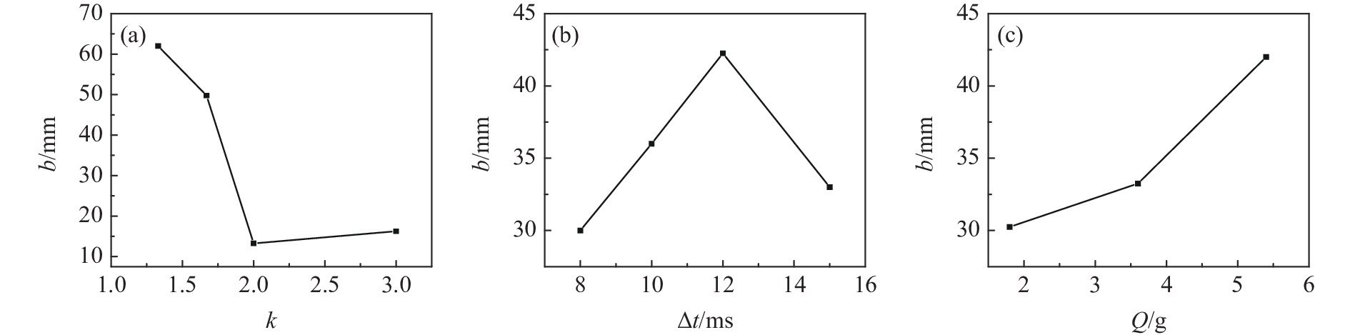
表 9 正交试验极差分析(预裂缝宽度)
Table 9. Extreme analysis for orthogonal experiments (pre-split crack width)
Factor $ \overline {{K_1}} $ $ \overline {{K_2}} $ $ \overline {{K_3}} $ $ \overline {{K_4}} $ R k 62.00 49.75 13.25 16.25 48.75 Δt 30.00 36.00 42.25 33.00 12.25 Q 30.25 33.25 42.00 35.75 11.75
下载: 导出CSV
-
[1] 刘昭桃. 岩石爆破技术的现状与发展浅谈[C]//中国铁道学会工程分会. 爆破工程技术交流论文集. 北京: 中国铁道出版社, 2018: 85−87.LIU Z T. Status and development of rock blasting technology [C]//Engineering Branch of China Railway Society. Proceedings of Blasting Engineering Technology Exchange, Beijing: China Railway Publishing House, 2018: 85−87. [2] 许守信, 黄绍威, 李二宝, 等. 复杂破碎岩体矩形聚能药包预裂爆破试验研究 [J]. 金属矿山, 2021(11): 55–63.XU S X, HUANG S W, LI E B, et al. Experimental study on pre-splitting blasting of rectangular shaped charge in complex fractured rock mass [J]. Metal Mine, 2021(11): 55–63. [3] BENDEZU M, ROMANEL C, ROEHL D. Finite element analysis of blast-induced fracture propagation in hard rocks [J]. Computers and Structures, 2017, 182: 1–13. [4] 王和平, 郭连军, 张大宁, 等. 大孤山铁矿预裂爆破研究与应用 [J]. 金属矿山, 2015(10): 18–23.WANG H P, GUO L J, ZHANG D N, et al. Application and research of pre-splitting blasting in dagushan iron mine [J]. Metal Mine, 2015(10): 18–23. [5] 杨仁树, 苏洪. 爆炸荷载下含预裂缝的裂纹扩展实验研究 [J]. 煤炭学报, 2019, 44(2): 482–489.YANG R S, SU H. Experimental study on crack propagation with pre-crack under explosion load [J]. Journal of China Coal Society, 2019, 44(2): 482–489. [6] 朱必勇, 焦文宇, 寇向宇, 等. 基于数值模拟的预裂爆破参数优化研究 [J]. 有色金属(矿山部分), 2019, 71(4): 32–36.ZHU B Y, JIAO W Y, KOU X Y, et al. Parameters optimization of pre-split blasting based on numerical simulation [J]. Non-Ferrous Metals (Mine Part), 2019, 71(4): 32–36. [7] MA J, LI X L, WANG J G, et al. Experimental study on vibration reduction technology of hole-by-hole presplitting blasting [J]. Geofluids, 2021, 2021: 1–10. [8] 叶海旺, 唐可, 万涛, 等. 时序控制预裂爆破参数优化及应用 [J]. 爆炸与冲击, 2017, 37(3): 502–509. doi: 10.11883/1001-1455(2017)03-0502-08YE H W, TANG K, WAN T, et al. Optimization of time sequence controlled pre-splitting blasting parameters and its application [J]. Explosion and Shock Waves, 2017, 37(3): 502–509. doi: 10.11883/1001-1455(2017)03-0502-08 [9] ZHANG B S, YANG Z P, YANG X M, et al. Presplit blasting technique in treating hard overlying strata: from numerical simulation to field practice [J]. Advances in Civil Engineering, 2021: 1–20. [10] 宫嘉辰, 陈士海. 隧道爆破力学模型相似材料配比的正交试验 [J]. 华侨大学学报(自然科学版), 2020, 41(2): 164–170.GONG J C, CHEN S H. Orthogonal test of similar materials ratio in tunnel blasting mechanical model [J]. Journal of Huaqiao University (Natural Science Edition), 2020, 41(2): 164–170. [11] 单仁亮, 黄宝龙, 蔚振廷, 等. 岩巷掘进准直眼掏槽爆破模型试验研究 [J]. 岩石力学与工程学报, 2012, 31(2): 256–264. doi: 10.3969/j.issn.1000-6915.2012.02.004SHAN R L, HUANG B L, WEI Z T, et al. Model test of quasi-parallel cut blasting in rock drivage [J]. Chinese Journal of Rock Mechanics and Engineering, 2012, 31(2): 256–264. doi: 10.3969/j.issn.1000-6915.2012.02.004 [12] 王正煜. 凤凰山石灰岩矿区边坡控制爆破参数优化研究[D]. 太原: 太原理工大学, 2021.WANG Z Y. Study on optimization of controlled blasting parameters of slope in Fenghuangshan limestone mining area [D]. Taiyuan: Taiyuan University of Technology, 2021. [13] 胡启文. 精确延时数(单)孔一响预裂爆破试验研究[D]. 昆明: 昆明理工大学, 2018.HU Q W. Study on preburst test of exact delay number (single) hole [D]. Kunming: Kunming University of Science and Technology, 2018. [14] 蒲传金, 杨鑫, 肖定军, 等. 爆炸载荷下双孔裂纹扩展的数值模拟研究 [J]. 振动与冲击, 2022, 41(15): 300–311.PU C J, YANG X, XIAO D J, et al. Numerical simulation study of double-hole crack propagation under explosive load [J]. Journal of Vibration and Shock, 2022, 41(15): 300–311. [15] WANG Z L, WANG H C, WANG J G, et al. Finite element analyses of constitutive models performance in the simulation of blast-induced rock cracks [J]. Computers and Geotechnics, 2021, 135: 1–12. [16] 李洪超. 岩石RHT模型理论及主要参数确定方法研究[D]. 北京: 中国矿业大学(北京), 2016.LI H C. Study on rock RHT model theory and determination method of main parameters [D]. Beijing: China University of Mining and Technology (Beijing), 2016. [17] 赵星宇, 白春华, 姚箭,等. 燃料空气炸药爆轰产物JWL状态方程参数计算 [J]. 兵工学报, 2020, 41(10): 1921–1929.ZHAO X Y, BAI C H, YAO J, et al. Parameters calculation of JWL EOS of FAE detonation products [J]. Acta Armamentarii, 2020, 41(10): 1921–1929. [18] 卢文波, 耿祥, 陈明, 等. 深埋地下厂房开挖程序及轮廓爆破方式比选研究 [J]. 岩石力学与工程学报, 2011, 30(8): 1531–1539.LU W B, GENG X, CHEN M, et al. Study of selection of excavation procedure and contour blasting method for deep underground powerhouse [J]. Chinese Journal of Rock Mechanics and Engineering, 2011, 30(8): 1531–1539. [19] 徐颖, 孟益平, 程玉生. 装药不耦合系数对爆破裂纹控制的试验研究 [J]. 岩石力学与工程学报, 2002(12): 1843–1847.XU Y, MENG Y P, CHENG Y S. Study on control of blast crack by decoupling charge index [J]. Chinese Journal of Rock Mechanics and Engineering, 2002(12): 1843–1847. [20] 何理, 钟冬望. 微差爆破地震波沿高程传播特性的试验研究 [J]. 化工矿物与加工, 2015, 44(5): 36–40. doi: 10.16283/j.cnki.hgkwyjg.2015.05.011HE L, ZHONG D W. Experimental study on propagation characteristics of millisecond blasting seismic waves along elevation [J]. Chemical Minerals and Processing, 2015, 44(5): 36–40. doi: 10.16283/j.cnki.hgkwyjg.2015.05.011 [21] 司剑峰, 钟冬望, 黄小武. 钻孔爆破孔间最佳延时时间模型试验研究 [J]. 金属矿山, 2015(6): 19–23.SI J F, ZHONG D W, HUANG X W. Experimental model of the optimal delay time in drilling blasting [J]. Metal Mine, 2015(6): 19–23. [22] 夏祥. 爆炸荷载作用下岩体损伤特征及安全阀值研究[D]. 武汉: 中国科学院研究生院, 2006.XIA X. Study on rock mass damage characteristics and safety threshold value under the action of explosion load [D]. Wuhan: Graduate School of Chinese Academy of Sciences, 2006. [23] YANG L J, YANG A Y, CHEN S Y, et al. Model experimental study on the effects of in situ stresses on pre-splitting blasting damage and strain development [J]. International Journal of Rock Mechanics and Mining Sciences, 2021, 138: 1–9. [24] 李洪伟, 吴延梦, 吴立辉, 等. 电子雷管起爆条件下隧道掏槽孔与辅助孔的延时优化试验研究 [J]. 高压物理学报, 2023, 37(1): 015301. doi: 10.11858/gywlxb.20220638LI H W, WU Y M, WU L H, et al. Experimental study on delay time optimization of tunnel cutting holes and caving holes under electronic detonator initiation condition [J]. Chinese Journal of High Pressure Physics, 2023, 37(1): 015301. doi: 10.11858/gywlxb.20220638 -

 下载:
下载:


计量
- 文章访问数: 1428
- HTML全文浏览量: 382
- PDF下载量: 30
