


Dynamic and Static Tensile Mechanical Properties of Glass Fiber Reinforced Plastics
-
摘要: 为系统地研究环氧树脂玻璃钢在静、动态拉伸载荷作用下的力学性能,采用材料测试系统和分离式霍普金森拉杆对材料进行拉伸试验,获得0.001~0.1 s−1及1128~1840 s−1应变率下的应力-应变曲线和相应的力学参数。结果表明,动态加载下环氧树脂玻璃钢的应变率增强效应较为明显。为此,引入动态增强因子描述环氧树脂玻璃钢在高应变率下力学性能的增强。采用扫描电镜对损伤断面进行观测,发现动态加载下纤维束平整断裂,而非静态加载下纤维拔出失效。相较于静态加载,动态拉伸载荷作用下玻璃钢的基体-纤维界面断裂韧度更高。基于环氧树脂玻璃钢在动态拉伸下的力学响应,引入宏观损伤累积量,建立一种考虑损伤的非线性拉伸本构模型。拟合结果表明,该模型整体上可以反映环氧树脂玻璃钢在动态拉伸载荷作用下的力学响应。Abstract: To systematically study the mechanical properties of glass fiber reinforced plastics, the stress-strain curves and corresponding mechanical parameters of glass fiber reinforced plastic with strain rates of 0.001–0.1 s−1 and 1128–1840 s−1 were obtained by material testing system (MTS) and split Hopkinson tensile bar (SHTB). The results show that the glass fiber reinforced plastic exhibits significant strain rate strengthening effect under dynamic loading. Therefore, the dynamic increasing factor was introduced to describe the strengthening effect of strain rate on mechanical properties of glass fiber reinforced plastics. Scanning electron microscopy (SEM) was used to observe and analyze the damaged section, and it was found that the fiber bundle was flatly fracture under dynamic loading, rather than failed by pulling out under static loading. In addition, the results show that the fracture toughness of the fiber-matrix interface under dynamic tensile loading is higher than that under static loading. Finally, based on the dynamic tensile mechanical response of glass fiber reinforced plastic, a nonlinear tensile constitutive model considering damage was established by introducing the macroscopic damage accumulation. Compared with the experimental results, the model as a whole can be used to characterize the dynamic tensile mechanical response of glass fiber reinforced plastic.
-
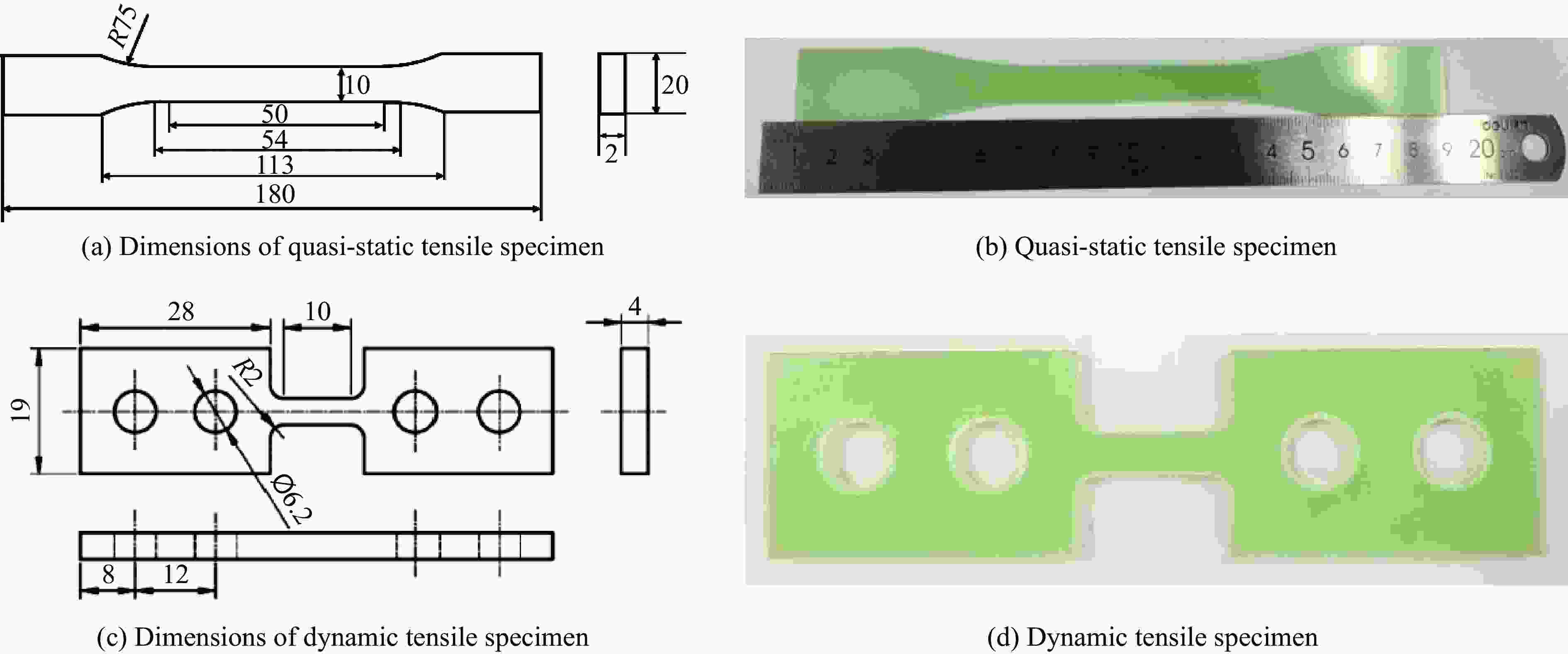
图 1 环氧树脂玻璃钢试样(单位:mm)
Figure 1. Specimens of glass fiber reinforced plastics (Unit: mm)

图 2 动态试验中使用的夹具(单位:mm)
Figure 2. Fixtures used in dynamic tensile experiments (Unit: mm)

图 4 准静态拉伸加载下试样的失效模式
Figure 4. Failure modes of the specimens under quasi-static tensile loading
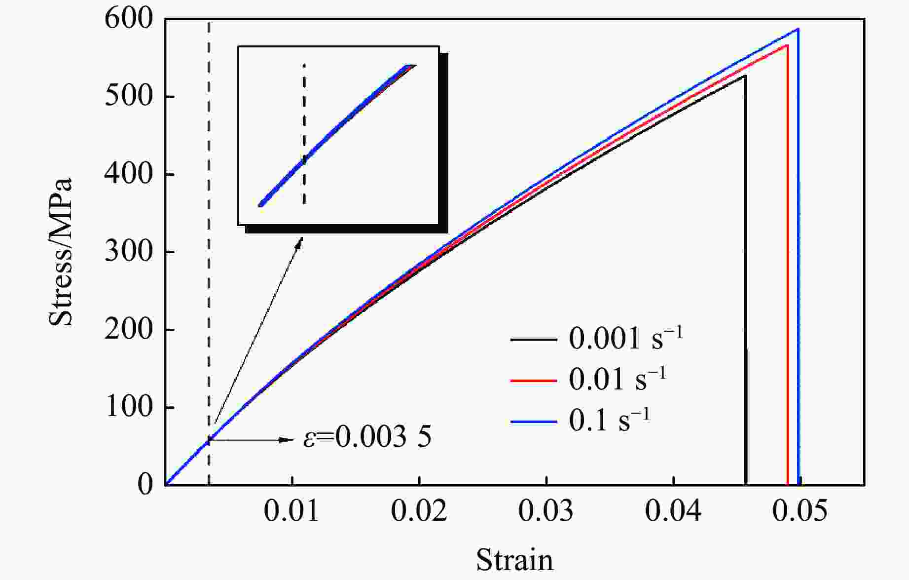
图 5 准静态拉伸加载下试样的应力-应变曲线
Figure 5. Stress-strain curves of specimens under quasi-static tensile loading
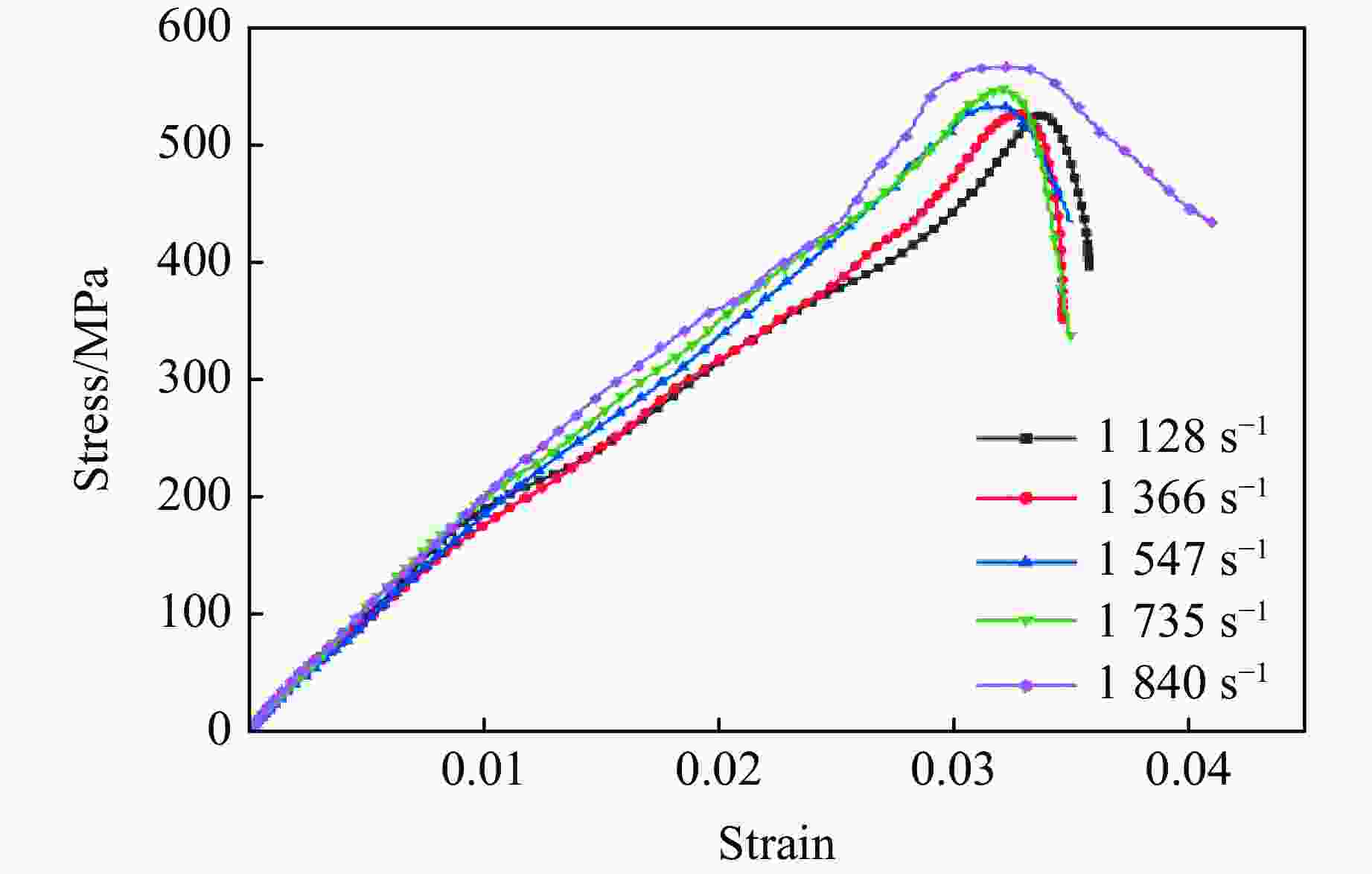
图 7 动态拉伸加载下试样的应力-应变曲线
Figure 7. Stress-strain curves of specimens under dynamic tensile loading

图 10 准静态拉伸试样断面的SEM图像
Figure 10. SEM observations of fracture surfaces of specimens under quasi-static tensile loading
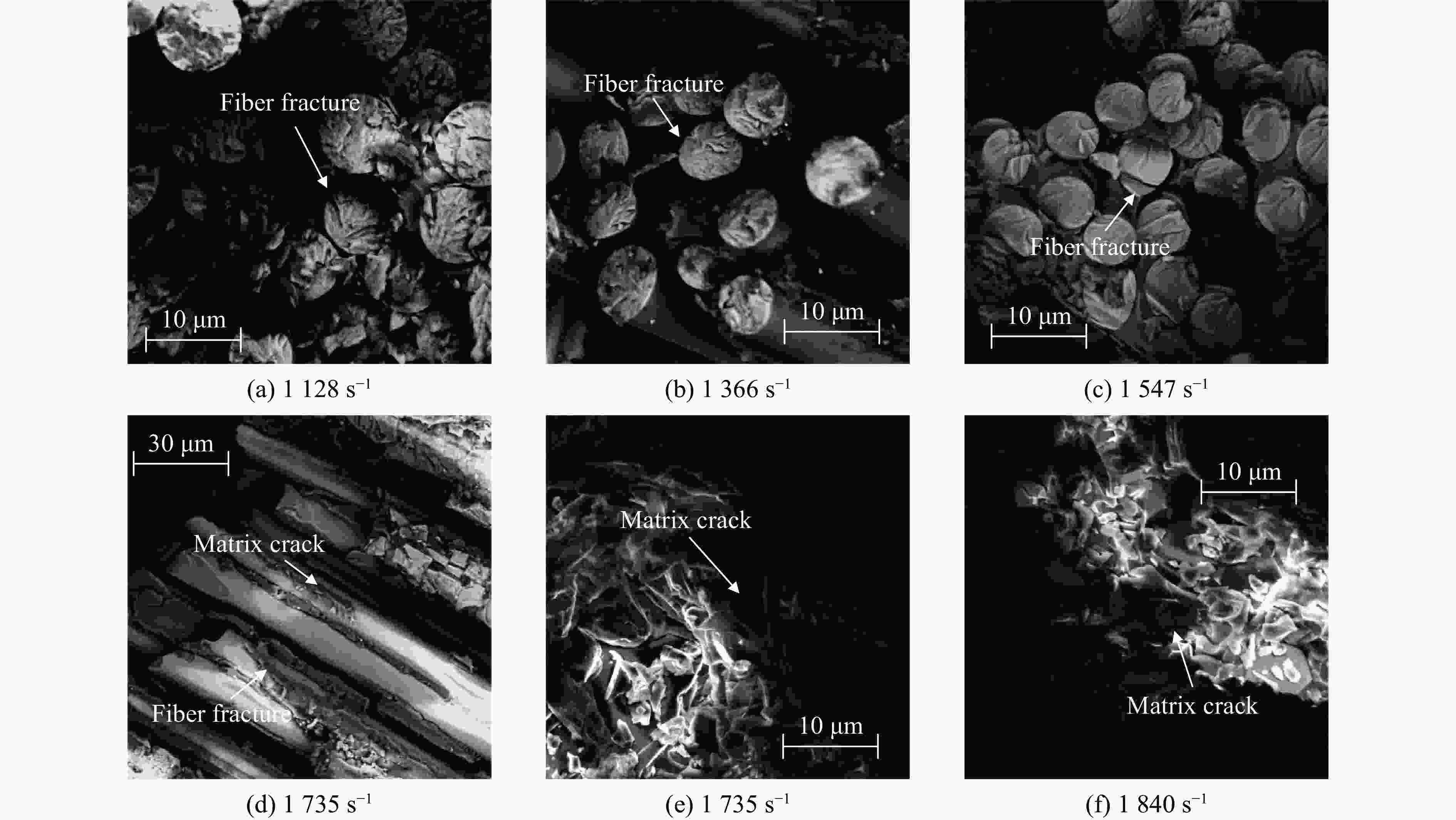
图 11 动态拉伸试样断面的SEM图像
Figure 11. SEM observations of fracture surfaces of specimens under dynamic tensile loading
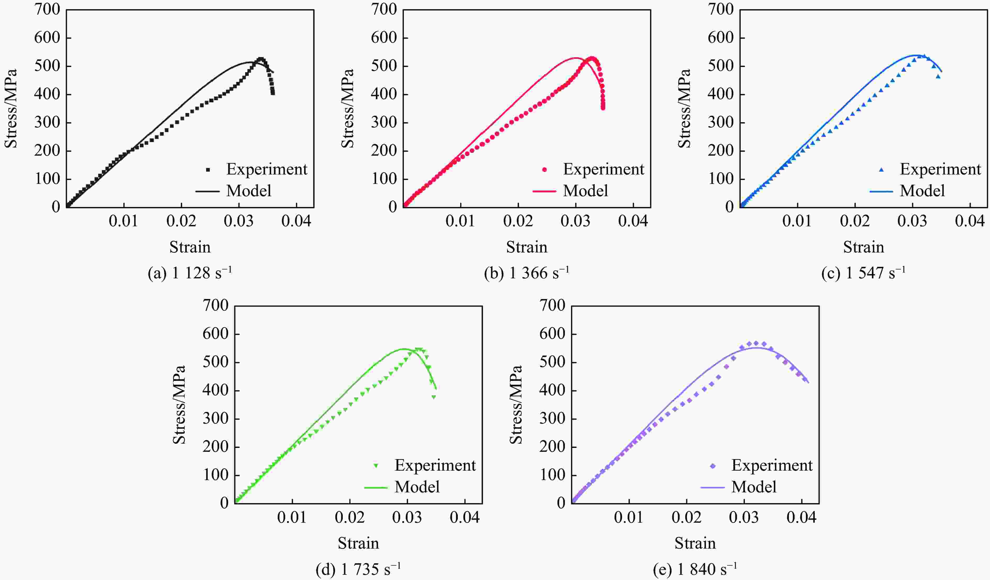
图 12 动态加载下基于Weibull分布的损伤本构模型计算与实验得到的应力-应变曲线对比
Figure 12. Comparison of stress-strain curves between model predictions and experiment results under dynamic tensile loading
表 1 环氧树脂玻璃钢的准静态拉伸力学参数
Table 1. Quasi-static tensile mechanical properties of glass fiber reinforced plastics
Strain rate/
s−1Young’s modulus/
GPaTensile strength/
MPaFailure strain/
%0.001 16.66 526.74 4.57 0.01 16.70 565.75 4.90 0.1 16.79 586.69 4.98  下载: 导出CSV
表 2 不同应变率下环氧树脂玻璃钢的拉伸力学参数
Table 2. Tensile mechanical properties of glass fiber reinforced plastics at various strain rates
Strain rate/
s−1Tensile strength/
MPaFailure strain/
%0.001 526.74 4.57 1128 527.15 3.58 1366 528.04 3.47 1547 533.99 3.51 1735 549.33 3.54 1840 568.09 4.12
下载: 导出CSV
-
[1] DEAN J, S-FALLAH A, BROWN P M, et al. Energy absorption during projectile perforation of lightweight sandwich panels with metallic fibre cores [J]. Composite Structures, 2011, 93(3): 1089–1095. doi: 10.1016/j.compstruct.2010.09.019 [2] LIU Y J, JIANG Z, WEN H M. Predicting impact induced delamination of FRP laminates [J]. International Journal of Impact Engineering, 2020, 137: 103436. doi: 10.1016/j.ijimpeng.2019.103436 [3] 田宏伟, 郭伟国. 平纹机织玻璃纤维增强复合材料面内压缩力学行为及破坏机制 [J]. 复合材料学报, 2010, 27(2): 133–139.TIAN H W, GUO W G. In-plane compressive mechanics behavior and failure mechanism for SW200/LWR-2 glass-woven composite [J]. Acta Materiae Compositae Sinica, 2010, 27(2): 133–139. [4] 朱文墨, 李刚, 杨小平, 等. 连续纤维增强树脂复合材料纵向压缩强度预测模型的发展及其影响因素 [J]. 复合材料学报, 2020, 37(1): 1–15.ZHU W M, LI G, YANG X P, et al. Development of prediction model and influencing factors of longitudinal compressive strength for continuous fiber reinforced polymer composites [J]. Acta Materiae Compositae Sinica, 2020, 37(1): 1–15. [5] 夏源明, 王兴, 杨报昌. 单向玻璃纤维增强环氧树脂在冲击拉伸时的一维本构方程 [J]. 复合材料学报, 1994, 11(4): 110–116.XIA Y M, WANG X, YANG B C. One dimensional constitutive equation of unidirectional glassfiber reinforced epoxy under tensile impact [J]. Acta Materiae Compositae Sinica, 1994, 11(4): 110–116. [6] SHOKRIEH M M, OMIDI M J. Tension behavior of unidirectional glass/epoxy composites under different strain rates [J]. Composite Structures, 2009, 88(4): 595–601. doi: 10.1016/j.compstruct.2008.06.012 [7] 吴健, 王纬波, 李泓运, 等. 中等应变率下单向玻璃纤维增强环氧树脂基复合材料的剪切本构关系 [J]. 复合材料学报, 2018, 35(2): 304–310.WU J, WANG W B, LI H Y, et al. Shear constitutive relationship of unidirectional glass fiber reinforced epoxy composites under intermediate strain rate [J]. Acta Materiae Compositae Sinica, 2018, 35(2): 304–310. [8] 刘子尚, 杨喆, 魏延鹏, 等. 单向增强玻璃钢复合材料静/动态拉伸实验研究 [J]. 爆炸与冲击, 2019, 39(9): 093101.LIU Z S, YANG Z, WEI Y P, et al. Static/dynamic tensiletest of unidirectional reinforced GFRP composites [J]. Explosion and Shock Waves, 2019, 39(9): 093101. [9] FERESHTEH-SANIEE F, MAJZOOBI G H, BAHRAMI M. An experimental study on the behavior of glass-epoxy composite at low strain rates [J]. Journal of Materials Processing Technology, 2005, 162: 39–45. [10] 张磊, 孙清, 王虎长, 等. E玻璃纤维增强环氧树脂基复合材料力学性能试验研究 [J]. 电力建设, 2010, 31(9): 118–121. doi: 10.3969/j.issn.1000-7229.2010.09.030ZHANG L, SUN Q, WANG H C, et al. Experimental study on the mechanical properties of E-glass fiber/epoxy composite material [J]. Electric Power Construction, 2010, 31(9): 118–121. doi: 10.3969/j.issn.1000-7229.2010.09.030 [11] 张硕, 姚宁, 吴继平, 等. 玻璃纤维增强环氧树脂复合材料的力学性能 [J]. 电工材料, 2016(1): 11–14, 19.ZHANG S, YAO N, WU J P, et al. Mechanical properties of glass fiber reinforced epoxy resin composite material [J]. Electrical Engineering Materials, 2016(1): 11–14, 19. [12] CHEN W S, MENG Q F, HAO H, et al. Quasi-static and dynamic tensile properties of fiberglass/epoxy laminate sheet [J]. Construction and Building Materials, 2017, 143: 247–258. doi: 10.1016/j.conbuildmat.2017.03.074 [13] NAIK N K, YERNAMMA P, THORAM N M, et al. High strain rate tensile behavior of woven fabric E-glass/epoxy composite [J]. Polymer Testing, 2010, 29(1): 14–22. doi: 10.1016/j.polymertesting.2009.08.010 [14] STAAB G H, GILAT A. High strain rate response of angle-ply glass/epoxy laminates [J]. Journal of Composite Materials, 1995, 29(10): 1308–1320. doi: 10.1177/002199839502901003 [15] GAO G F, LI Y C. Dynamic behavior of a woven glass-fiber-reinforced polymer composite at high strain rates and its dynamic constitutive relationship [J]. Mechanics of Advanced Materials and Structures, 2017, 24(13): 1086–1093. doi: 10.1080/15376494.2016.1227493 [16] 许沭华, 王肖钧, 张刚明, 等. Kevlar纤维增强复合材料动态压缩力学性能实验研究 [J]. 实验力学, 2001, 16(1): 26–33.XU S H, WANG X J, ZHANG G M, et al. Experimental investigation on the dynamic compression properties of kevlar fiber-rainforced composite laminates [J]. Journal of Experimental Mechanics, 2001, 16(1): 26–33. [17] HU J X, YIN S, YU T X, et al. Dynamic compressive behavior of woven flax-epoxy-laminated composites [J]. International Journal of Impact Engineering, 2018, 117: 63–74. doi: 10.1016/j.ijimpeng.2018.03.004 [18] POURNOORI N, SOARES G C, ORELL O, et al. Adiabatic heating and damage onset in a pultruded glass fiber reinforced composite under compressive loading at different strain rates [J]. International Journal of Impact Engineering, 2021, 147: 103728. [19] 哈维尔, 刘问, 孟鑫淼, 等. 基于断裂理论的竹纤维复合材料拉伸强度的尺寸效应研究 [J]. 复合材料科学与工程, 2021(2): 11–18.NCHAMA J, LIU W, MENG X M, et al. Size effect study of tensile strength of bamboo fiber composites on basis of fracture theory [J]. Composites Science and Engineering, 2021(2): 11–18. [20] 阮班超, 史同亚, 王永刚. E玻璃纤维增强环氧树脂基复合材料轴向拉伸力学性能的应变率效应 [J]. 复合材料学报, 2018, 35(10): 2715–2722.RUAN B C, SHI T Y, WANG Y G. Influence of strain rate on tensile mechanical behavior of E glass fiber reinforced epoxy resin composites [J]. Acta Materiae Compositae Sinica, 2018, 35(10): 2715–2722. [21] CHEN C Y, ZHANG C, LIU C L, et al. Rate-dependent tensile failure behavior of short fiber reinforced PEEK [J]. Composites Part B: Engineering, 2018, 136: 187–196. doi: 10.1016/j.compositesb.2017.10.031 [22] NANDLALL D, WILLIAMS K, VAZIRI R. Numerical simulation of the ballistic response of GRP plates [J]. Composites Science and Technology, 1998, 58(9): 1463–1469. doi: 10.1016/S0266-3538(98)00030-X [23] 段茜. 复合应力状态下聚酰胺的粘弹-塑性本构研究 [D]. 太原: 太原理工大学, 2018: 14−18.DUAN Q. Viscoelastic-plastic constitutive model of polyamide under combined stress state [D]. Taiyuan: Taiyuan University of Technology, 2018: 14−18. -

 下载:
下载:


计量
- 文章访问数: 462
- HTML全文浏览量: 340
- PDF下载量: 61
