Numerical Simulation and Parametric Analysis of High-Pressure Gas-Driven Shock Tube
-
摘要: 爆炸荷载作用下建筑构件的动态响应与损伤破坏的试验研究对于结构抗爆设计具有重要的参考价值。为了探究激波管参数对末端荷载峰值和持时的影响,首先,基于商用有限元分析软件ANSYS/LS-DYNA开展了典型激波管试验的数值模拟,通过对比膨胀段末端反射超压和测试构件的挠度时程,验证了激波管有限元模型、参数取值和数值分析方法的准确性;然后,设计了末端尺寸为3 m×3 m的激波管,开展了激波管几何参数和驱动段超压对末端反射超压的参数影响分析,结果表明:超压峰值和持时随驱动段长度、直径和超压的增大而增加,随膨胀段角度减小而增加;最后,给出了基于反射超压峰值和持时的激波管设计方法,并通过设计算例进行了验证。Abstract: It has great importance for the blast-resistant design of the structures to study the dynamic response and damage failure of structural components under explosion loads. This work focused on analyzing the influences of the shock tube’s parameters on the loads at the end of the driven section. Based on the ANSYS/LS-DYNA, the numerical simulation of the shock tube is conducted. The accuracy of the finite element model, parameters values, and the numerical simulation method are verified by comparing the numerical simulation results, such as overpressure-time histories and the deflection response of the reinforced concrete slabs, with the experimental results. Furthermore, a shock tube with a size of 3 m×3 m at the end of the driven section is designed. The influences of the shock tube’s geometric parameters and its inner overpressure on the loads at the end of the driven section are analyzed. The results show that the peak overpressure and positive time duration increased with the increase of the length, diameter, and pressure of the driver section. The results also show that the peak overpressure and positive time duration increased with the decrease of the angle of the expansion section. Finally, the design method of the shock tube based on peak overpressure and positive time duration is given, which was verified by the designed examples.
-
Key words:
- shock tube /
- design method /
- driver section /
- driven section
-
表 1 理想气体材料参数
Table 1. Parameters of gas
Gas type p/MPa ${\rho {_0}}$/(kg·m−3) ${e{_0}}$/(MJ·m−3) Air 0.1 1.29 0.25 High-pressure gas 0.1n 1.29n 0.25n 表 2 试验工况
Table 2. Test cases
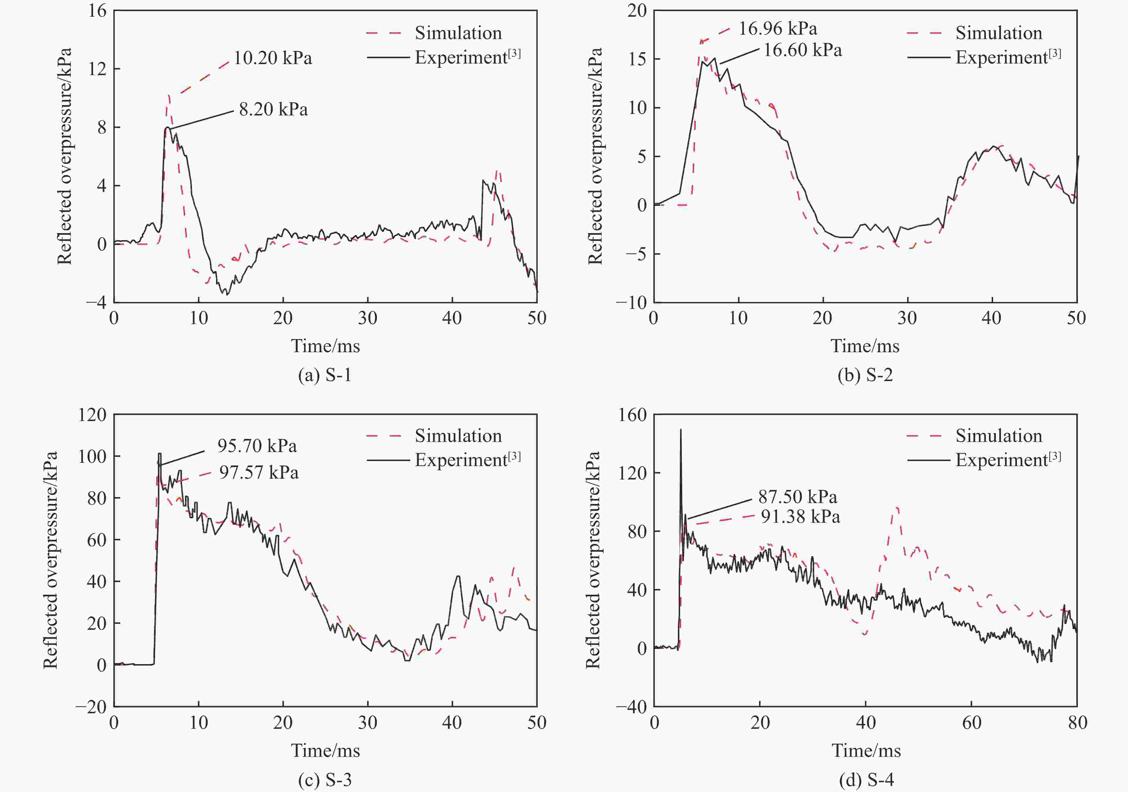
Case Overpressure of driver section/kPa Length of driver section/mm S-1 61.4 305 S-2 80.7 1 830 S-3 697.1 2 745 S-4 637.1 4 880 表 3 RC板试验工况
Table 3. Test cases of RC slabs
Case Boundary conditions Thickness of RC slabs/mm Concrete strength/MPa Overpressure of driver section/kPa Length of driver section/mm S-5 Simply-supported 75 60.0 80 1 830 S-6 Simply-supported 75 60.0 133 1 830 S-7 Fixed 75 49.5 125 1 830 表 4 拟合系数
Table 4. Fitted coefficients
A B C D E F G H –8.09 –16.88 405.54 –2.90 41.19 –93.76 9.75 542.06 I J K L M N O –2.09 11.73 –11.78 –231.52 –326.53 31.10 –49.57 A′ B′ C′ D′ E′ F′ G′ H′ –0.61 1.22 –26.59 –0.20 –2.10 3.79 0.41 –11.95 I′ J′ K′ L′ M′ N′ O′ –0.34 2.57 1.62 13.90 5.97 0.99 1.24 表 5 设计工况
Table 5. Designed cases
Designed case Δp/kPa Δt/ms l/m d/m p/MPa θ/(°) Designed Calc. Sim. Designed Calc. Sim. D-1 130 136.57 127.97 17 17.99 17.70 3 0.7 0.5 10.55 D-2 350 352.25 357.10 15 16.08 14.85 3 0.7 1.5 10.55 -
[1] BREWER T R, CRAWFORD J E, MORRILL K B, et al. Design, analysis, and testing of a blast-resistant building façade [J]. International Journal of Computational Methods and Experimental Measurements, 2016, 4(3): 191–200. doi: 10.2495/CMEM-V4-N3-191-200 [2] OESTERLE M G. Blast simulator wall tests: experimental methods and mitigation strategies for reinforced concrete and concrete masonry [D]. San Diego: University of California, 2009: 78–83. [3] JACQUES E. Blast retrofit of reinforced concrete walls and slabs [D]. Canada: University of Ottawa, 2011: 40–122. [4] OPALKA K O, PERSON R J. CFD design studies of an advanced concept driver for a large blast/thermal simulator [C]//AIP Conference Proceedings. USA: American Institute of Physics, 1990, 208(1): 885–890. [5] 任辉启, 王世合, 周松柏, 等. 大型爆炸波模拟装置研制及其应用 [C]//第十六届全国激波与激波管学术会议论文集, 2014.REN H Q, WANG S H, ZHOU S B, et al. The development and application of large blast wave simulator[C]//The 16th National Conference on Shock Waves and Shock Tubes, 2014. [6] CLUBLEY S K. Steel sections subject to a long-duration blast [J]. Proceedings of the Institution of Civil Engineers-Structures and Buildings, 2013, 166(6): 273–281. doi: 10.1680/stbu.12.00007 [7] CLUBLEY S K. Non-linear long duration blast loading of cylindrical shell structures [J]. Engineering Structures, 2014, 59: 113–126. doi: 10.1016/j.engstruct.2013.10.030 [8] CANNON L, CLUBLEY S K. Structural response of simple partially-clad steel frames to long-duration blast loading [J]. Structures, 2021, 32: 1260–1270. [9] LLOYD A. Performance of reinforced concrete columns under shock tube induced shock wave loading [D]. Canada: University of Ottawa, 2010: 43–53. [10] REMENNIKOV A, UY B, CHAN E, et al. The Australian national facility for physical blast simulation [C]//The 2019 Coal Operators Conference. Wollongong, Australian, 2019. [11] DALLRIVA F D, JOHNSONO C F, O'DANIEL J L, et al. Blast load simulator experiments for computational model validation: report 1 [R]. U. S. Army Engineer Research and Development Center, Vicksburg United States, 2016. [12] ANDREOTTI R, COLOMBO M, GUARDONE A, et al. Performance of a shock tube facility for impact response of structures [J]. International Journal of Non-Linear Mechanics, 2015, 72: 53–66. doi: 10.1016/j.ijnonlinmec.2015.02.010 [13] AUNE V, CASADEI F, VALSA G, et al. A shock tube used to study the dynamic response of blast-loaded plates [J]. Multidisciplinary Digital Publishing Institute Proceedings, 2018, 2(8): 503. [14] ISMAIL A, EZZELDIN M, EL-DAKHAKHNI W, et al. Blast load simulation using conical shock tube systems [J]. International Journal of Protective Structures, 2020, 11(2): 135–158. doi: 10.1177/2041419619858098 [15] LS-DYNA. Keyword user’s manual [Z]. Livermore, California, USA: Livermore Software Technology Corporation, 2020. [16] STOUFFER D C, DAME L T. Inelastic deformation of metals: models, mechanical properties, and metallurgy [M]. John Wiley & Sons, 1996: 72–73. -


 下载:
下载:

