Progress on Atomic Simulations of Phase Transition of Iron under Dynamic Loading
-
摘要: 铁的
$\alpha $ ↔$\varepsilon$ 相变是金属高压相变研究领域的经典范例,随着测试技术的进步,其相变机制与动力学研究不断深入,基于激光加载的原位X射线观察结合非平衡分子动力学模拟研究是解决该问题最有效的手段之一。为此,综述了铁在动态载荷下塑性与相变的原子模拟研究进展,综合分析了铁的高压势函数,平面应变加载下晶体的各向异性、冲击强度、应变率、应变梯度、各种初始晶体缺陷等对铁相变机制的影响,以及铁的相变与层裂,同时报道了铁在非平面加载下响应规律研究的最新进展,最后进行了归纳总结和展望。Abstract:$\alpha $ ↔$\varepsilon $ transformation of iron is a prototype of high-pressure phase transition in metals. With the progress of detecting technology, mechanism and dynamics of the phase transition have being investigated in depth. Laser-driven in situ X-ray observation combined with non-equilibrium molecular dynamics simulation is one of the most effective approach to the issue. In present paper, the progress of atomic investigations on plasticity and phase transformation of iron under dynamic loading is reviewed. The effects of high-pressure interatomic potential of iron, crystal anisotropy, impact strength, strain rate, strain gradient and various initial crystal defects on phase transformation mechanism, phase transformation and spalling of iron are analyzed. Meanwhile, the latest progress of our researches on nonplanar-loading responses of iron is reported. Finally, the conclusion and prospect are given.-
Key words:
- high-pressure structural transition /
- plasticity /
- spall /
- molecular dynamics /
- interatomic potential /
- iron
-
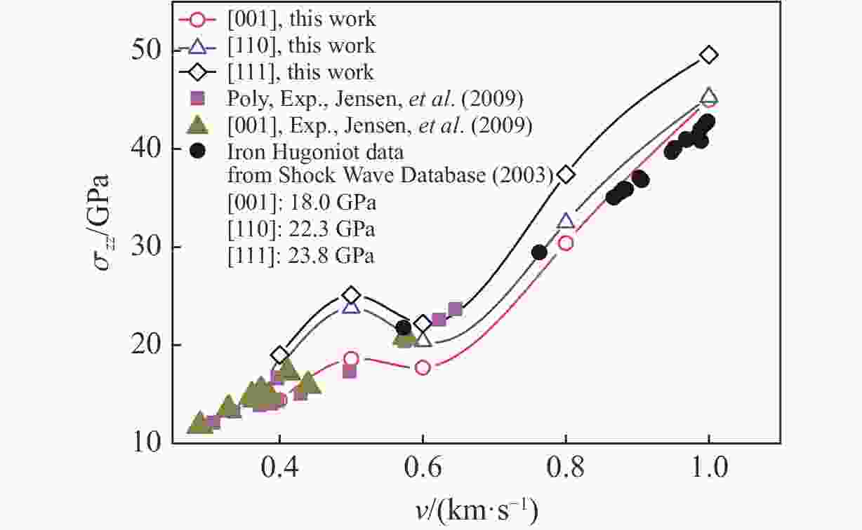
图 3 (a) MAEAM势预测的物态方程与实验及第一原理计算结果的对比,(b) 采用MAEAM势与改进的Ackland势的计算结果对比[49, 52-54]
Figure 3. (a) Comparison of equations of states predicted by MAEAM potential with experiments and the first-principle calculations, (b) Comparison of the results between MAEAM potential and modified Ackland potential[49, 52-54]
图 6 实现高应变率加卸载的3种方法:(a)活塞加载,(b)对称撞击,(c)均匀单轴压缩(“M”表示材料,箭头表示活塞或材料的运动方向,灰色梯度表示材料受到碰撞时形成的冲击波)
Figure 6. Three simulation approaches of de-/compression under high strain rates: (a) piston loadings, (b) symmetric impingements and (c) uniform uniaxial compressions, where “M” represents materials and the arrows show the motion directions of the piston and materials, and shock waves initiated around the impinging moment are illustrated by the grayscale
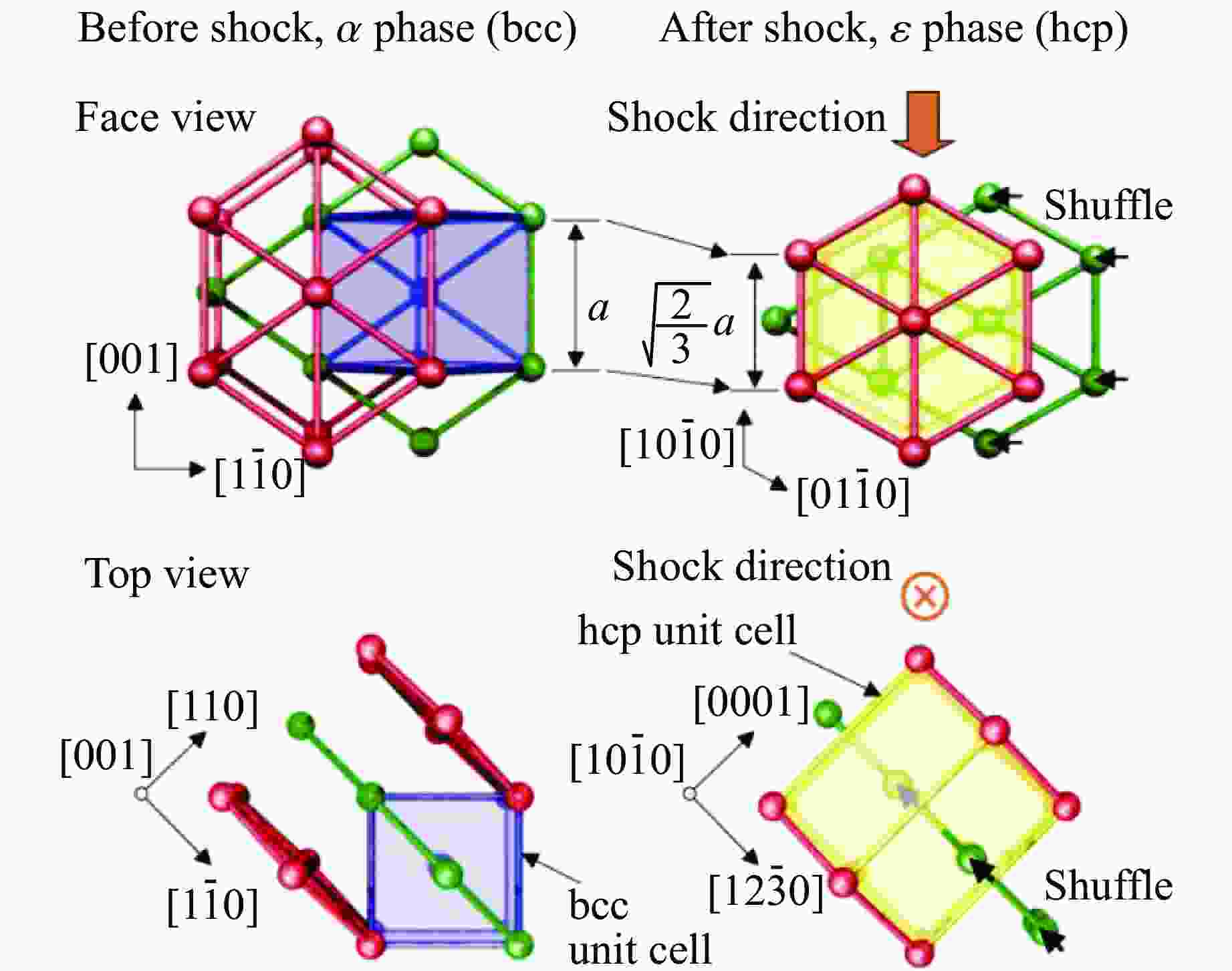
图 8 (a)不同冲击晶向与冲击强度下单晶铁的相变(红色、黄色、浅蓝色和深蓝色分别表示hcp原子、fcc原子、bcc原子和缺陷原子),(b)冲击晶向与惯习面的关系[34]
Figure 8. (a) Phase transition of single crystalline iron under different shock directions and shock strength (The meaning of the colors is: red (hcp atoms), yellow (fcc atoms), light blue (bcc atoms) and dark blue (defects).); (b) relationship between the shock direction and habit plane[34]
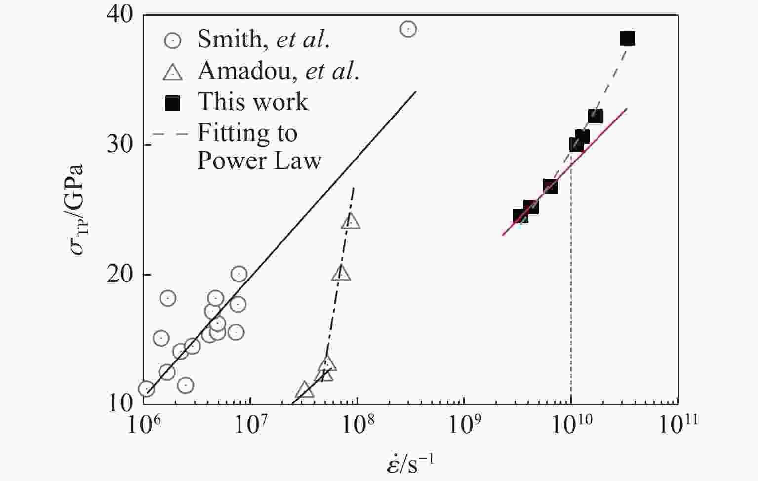
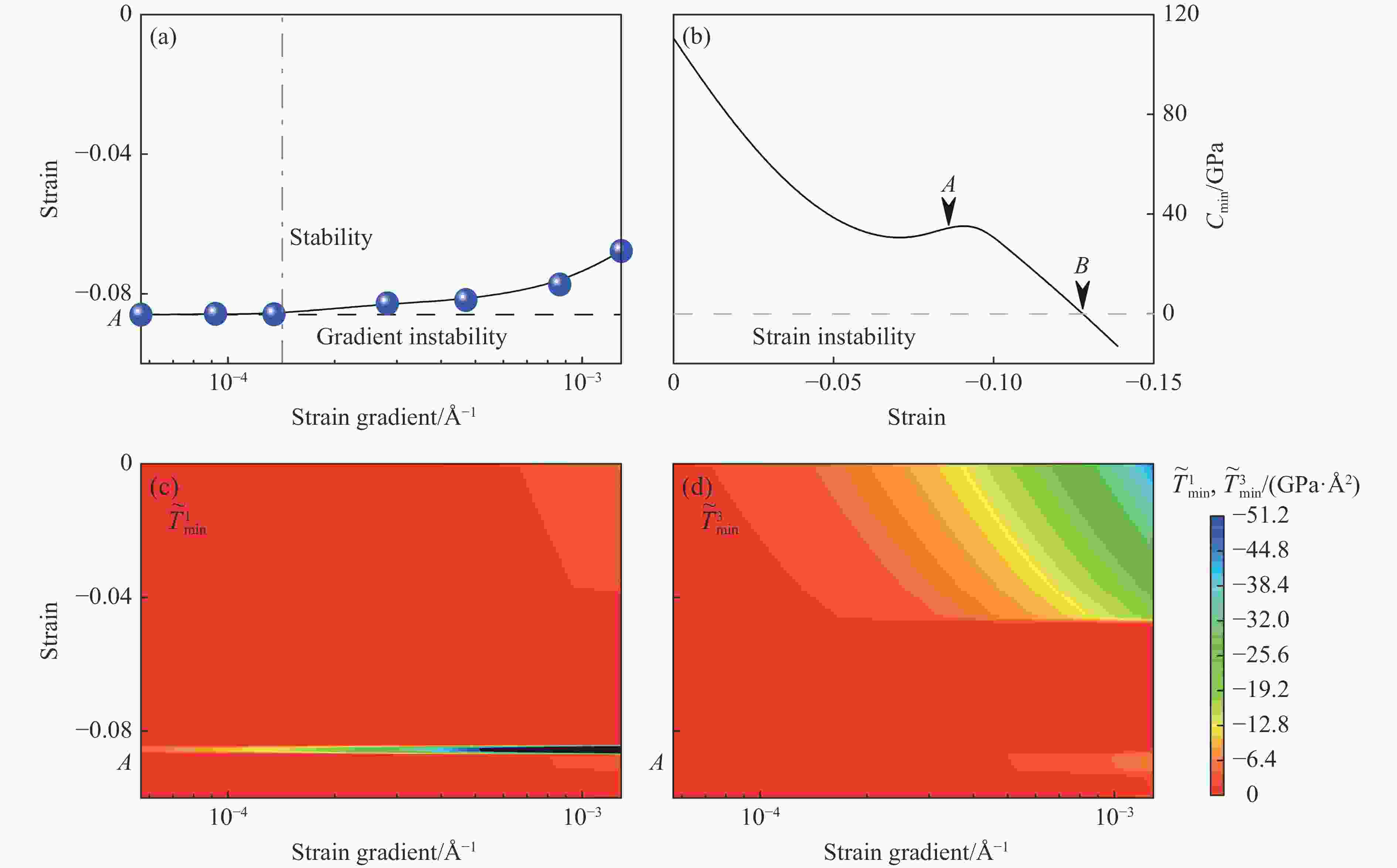
图 12 (a)斜波加载下临界失稳应变与应变梯度的依赖关系;(b)
$ \widetilde {{{B}}} $ 的最小本征值(Cmin)随单轴应变的变化;(c)~(d)分别以$ {\widetilde {T}}_{\rm{min}}^{1} $ 和$ {\widetilde {T}}_{\rm{min}}^{3} $ 表示的应变-应变梯度空间中的等高图($ {\widetilde {T}}_{\rm{min}}^{1} $ 和$ {\widetilde {T}}_{\rm{min}}^{3} $ 分别为$ \widetilde {{T}} $ 沿x和z方向分量的最小本征值,图中所有的A对应于相同的应变)[62]Figure 12. (a) Critical instability strain versus strain gradient under ramp compressions; (b) minimumeigenvalue of
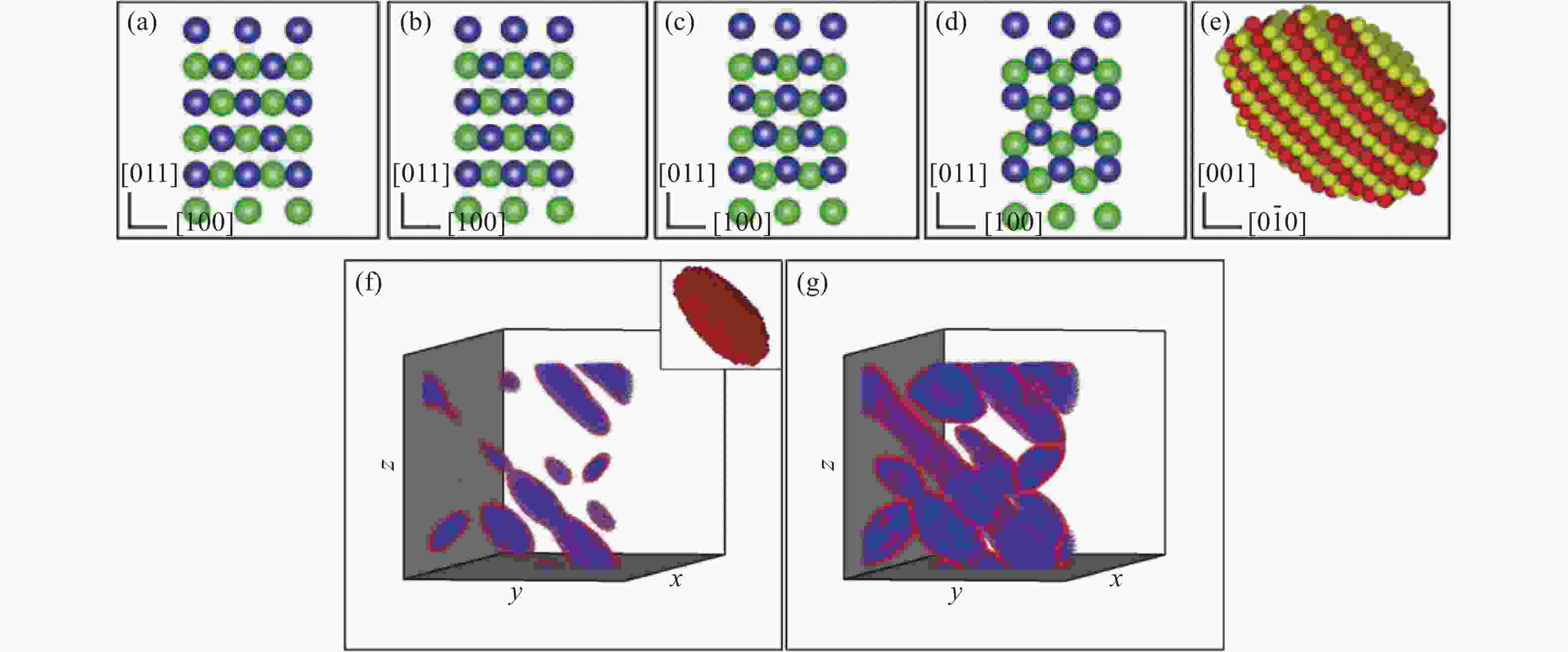
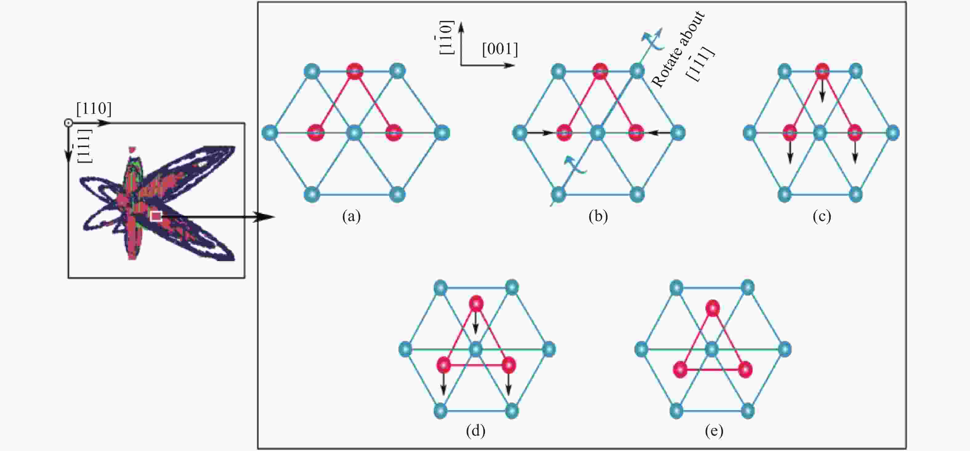
$ \widetilde {{{B}}} $ versus uniaxial strain; (c) and (d) are the contour plot$ {\widetilde {T}}_{\rm{min}}^{1} $ and$ {\widetilde {T}}_{\rm{min}}^{3} $ in the strain vs. strain gradient space, where$ {\widetilde {T}}_{\rm{min}}^{1} $ and$ {\widetilde {T}}_{\rm{min}}^{3} $ are the minimum eigenvalue of the x- and z-component of$ \widetilde {{T}} $ (In the figures, “A” corresponds to the same strain.)[62]图 16 含有孪晶的双晶铁样品在最大粒子速度为0.4 km/s的斜波压缩下31 ps时的局部构型(红色表示hcp原子,蓝色表示bcc原子,右图hcp晶胞中黄色的原子面对应于左图中黄色方框标记的原子面)[74]
Figure 16. Local configuration of bicrystal iron sample containing a twin at 31 ps under ramp compressions with a maximum particle velocity of 0.4 km/s (Red denotes hcp atom and blue denotes bcc atom. The right figure shows a unit cell of hcp phase, where the yellow atomic face corresponds to the atomic face marked with yellow square in the left figure.)[74]
图 17 在0.5 km/s的粒子速度下
$\varSigma3$ 扭转晶界(a)与$\varSigma3$ 倾斜晶界(b)的冲击塑性与相变(冲击波沿z方向传播,在两种样品中分别对应于<110>和<111>晶向)[75]Figure 17. Shock-induced plasticity and phase transition of
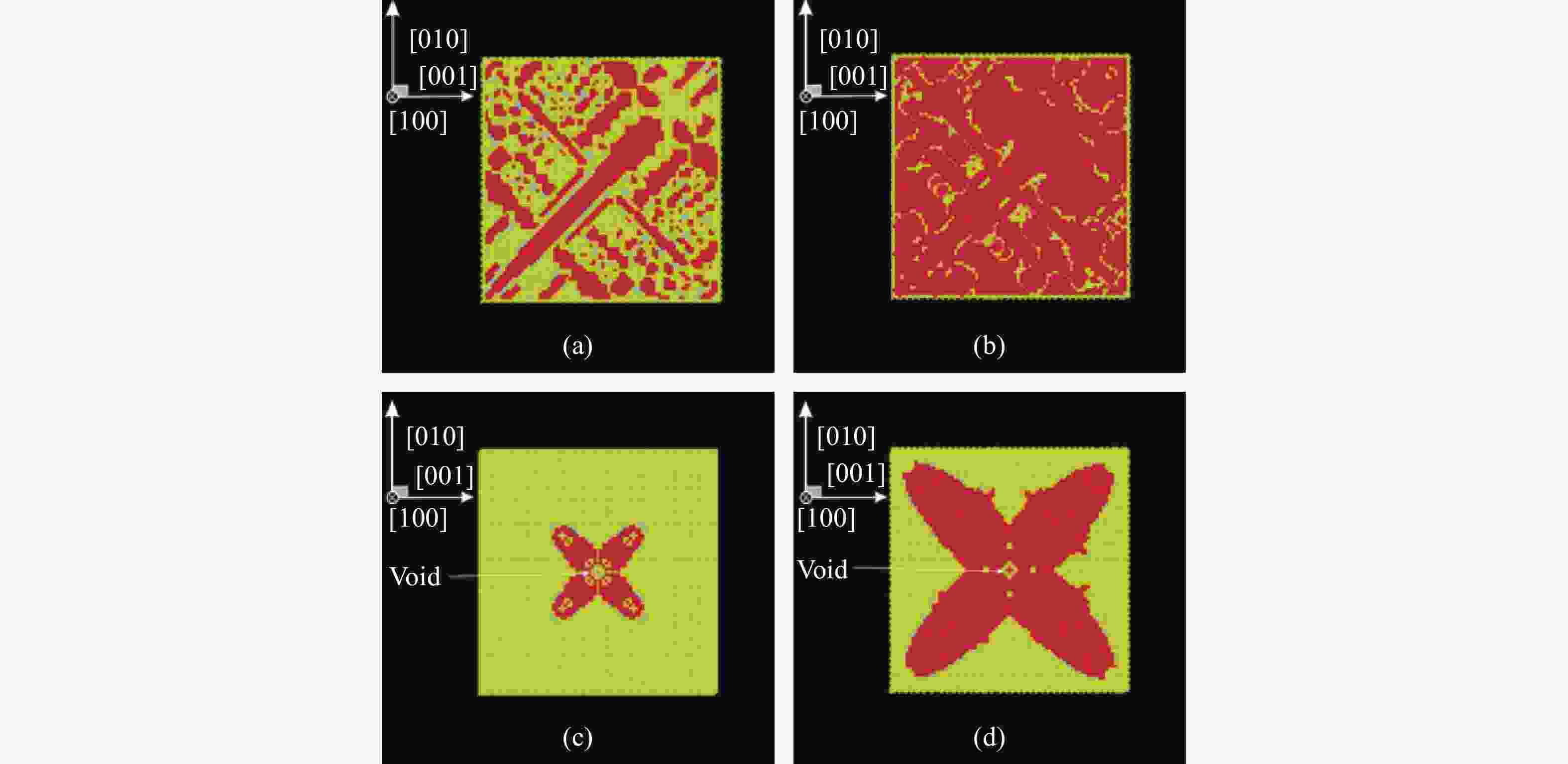
$\varSigma3$ twist grain boundary (a) and$\varSigma3$ tilt grain boundary (b) under the shock with a particle velocity of 0.5 km/s, where shock wave propagates along z direction, corresponding to <110> and <111> crystallographic direction, respectively[75]图 20 激光冲击实验回收的铁样品:(a)样品初始温度293 K,层裂面处的最高加载状态处于
$\alpha$ →$\varepsilon $ 相变边界上;(b) 样品初始温度673 K,层裂面处的最高加载状态处于两相共存区[81]Figure 20. Iron samples recovered after laser shocks (a) at 293 K, where the maximum loading state of the spall plane is on the
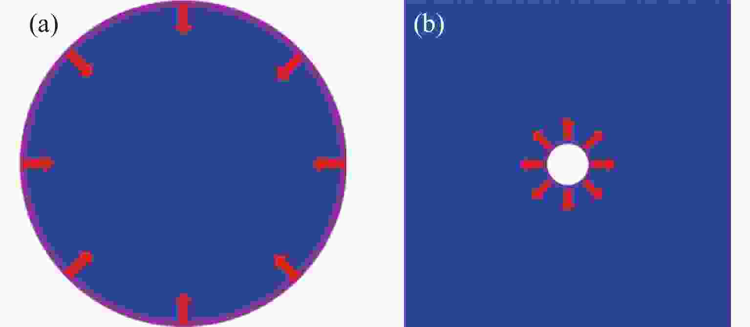
$\alpha $ →$\varepsilon $ phase transition boundary, and (b) at 673 K, where the maximum loading state of the spall plane locates at the two-phase-coexistence region[81]图 21 柱面内爆(a)和外爆(b)冲击加载示意图(蓝色表示试样,紫色圆环表示柱形势能面,红色箭头表示加载方向)
Figure 21. Schematic diagram of the shock loading by cylindrical (a) implosion and (b) explosion (The blue part represents the sample, the purple ring represents the energy surface of the column, and the red arrow represents the loading direction.)
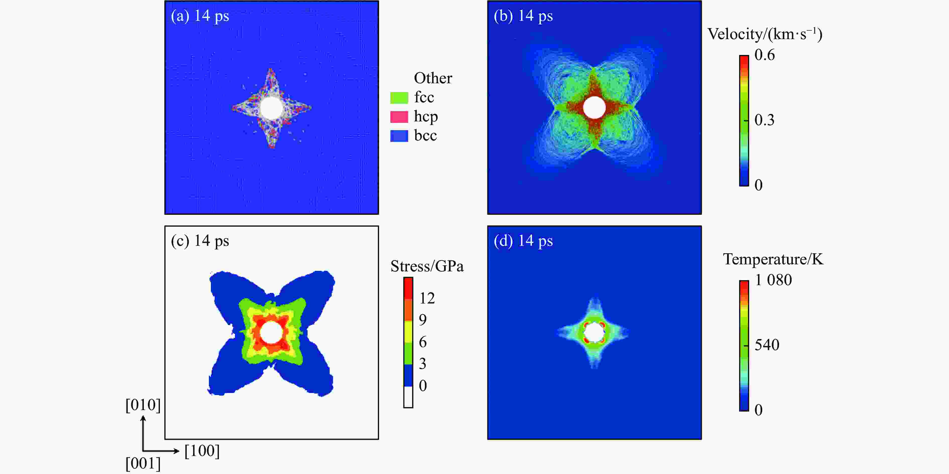
图 22 (a)柱面轴沿单晶Fe [001]晶向在内爆冲击下垂直于柱面轴的横截面内的原子速率分布,(b)10 ps时垂直柱面轴横截面内的局域温度分布
Figure 22. (a) Atom velocity distribution in the cross section perpendicular to the cylindrical axis under implosion impact along [001] direction of Fe single crystal, and (b) the local temperature distribution in the cross section perpendicular to the cylindrical axis at 10 ps
图 23 柱面轴沿单晶Fe [001]晶向在内爆冲击下(vp = 0.6 km/s)局域微结构随时间的演变(红色表示hcp结构原子,绿色表示以层错形式出现的fcc结构原子,灰色表示位错线周围的其他结构类型的原子,为清晰起见,未相变的bcc结构原子已被删除)
Figure 23. Evolutions of local microstructures with time under the implosive impacting with the cylindrical axis along [001] direction of Fe single crystal (vp = 0.6 km/s) (Red indicates hcp atoms, green indicates fcc atoms in the forms of stacking faults, and gray indicates other atoms distributed around dislocation lines. For clarity, bcc atoms without phase transition have been removed.)
a1 a2 a3 a4 a5 a6 A1 A2 −31.807065 36.158663 12.237970 −72.863506 156.864024 200.148093 72.868383 −100.944857 r1 r2 r3 r4 r5 r6 R1 R2 1.450000 1.430000 1.080000 0.990000 0.930000 0.866025 1.300000 1.200000 m n F0 g0 $\alpha $ $\;\beta $ $\gamma $ 55.847 0.289 2.1952807 1 9.17×10⁻³ 4.15 5.01 $\;\rho $e Pe k0 k1 k2 k3 kc 10.875221 10.443309 −3.6918979 −0.3369724 −0.4937837 −0.3210981 0.3 表 3 改进的Ackland势与MAEAM势预测的铁主要物理性质与有关第一原理计算及实验结果的对比
Table 3. Comparisons of key properties of iron predicted using modified Ackland potential and MAEAM potential with the first-principle-base calculations or experimental results
Method Basic properties a0/Å $E{\rm{_c}} $/eV $E{ \rm{^{f,1}_{1v} }}$/eV $E{ \rm{^{f,2}_{1v} }} $/eV ${\gamma }{_{\rm{unf} }^{110}}$/(J·m−2) ${\gamma }{_{\rm{unf} }^{112}}$/(J·m−2) Modified-Ackland 2.866 4.316 1.89 1.83 0.669 0.769 MAEAM 2.8606 4.28 2.09 1.86 0.652 0.710 Ref. 2.8606[41]
2.88[42]
2.86[43]4.28[44] 2.07[42]
1.95[43]2.0[37] 0.47 (GGA)[45]
0.59 (LDA)[45]Method Basic properties Elastic Vibrational $\Delta $Efcc-bcc/eV $\Delta $Ehcp-bcc/eV C11/GPa C12/GPa C44/GPa ${\nu }{_{N}^{ {\rm{T} }1}}$ /THz Modified-Ackland 0.135 0.191 243.7 145.3 116.3 10.83 MAEAM 0.034 0.016 243 138 127 9.39 Ref. 243.1[46]
243.0[47]138.1[46]
138.0[47]121.9[46]
127.0[47]9.26[48] Method Vibrational Others ${\nu }{_{N}^{ {\rm{T} }2} }$/THz ${\nu }{_{N}^{\rm{L} }}$/THz ${\nu }{_{H}}$/THz ${\nu }{_{P}}$/THz $p{_T}$/GPa $T{\rm{_m}}$/K Modified-Ackland 5.99 3.85 9.77 8.61 13.75 MAEAM 5.93 2.86 9.18 7.16 11 1807 Ref. 6.46[48] 4.47[48] 8.49[48] 7.19[48] 10[49]
10.5[50]1813[51] -
[1] VOČADLO L, ALFÈ D, GILLAN M J, et al. Possible thermal and chemical stabilization of body-centred-cubic iron in the Earth’s core [J]. Nature, 2003, 424(6948): 536–539. doi: 10.1038/nature01829 [2] BELONOSHKO A B, AHUJA R, JOHANSSON B. Stability of the body-centred-cubic phase of iron in the Earth’s inner core [J]. Nature, 2003, 424(6952): 1032–1034. doi: 10.1038/nature01954 [3] BAXEVANIS T, PARRINELLO A F, LAGOUDAS D C. On the fracture toughness enhancement due to stress-induced phase transformation in shape memory alloys [J]. International Journal of Plasticity, 2013, 50: 158–169. doi: 10.1016/J.IJPLAS.2013.04.007 [4] GUNKELMANN N, BRINGA E M, URBASSEK H M. Influence of phase transition on shock-induced spallation in nanocrystalline iron [J]. Journal of Applied Physics, 2015, 118(18): 185902. doi: 10.1063/1.4935452 [5] CHERKAOUI M, BERVEILLER M, LEMOINE X. Couplings between plasticity and martensitic phase transformation: overall behavior of polycrystalline TRIP steels [J]. International Journal of Plasticity, 2000, 16(10/11): 1215–1241. doi: 10.1016/S0749-6419(00)00008-5 [6] TAKAHASHI T, BASSETT W A. High-pressure polymorph of iron [J]. Science, 1964, 145(3631): 483–486. doi: 10.1126/science.145.3631.483 [7] BANCROFT D, PETERSON E L, MINSHALL S. Polymorphism of iron at high pressure [J]. Journal of Applied Physics, 1956, 27(3): 291–298. doi: 10.1063/1.1722359 [8] 唐志平. 冲击相变[M]. 北京: 科学出版社, 2008.TANG Z P. Shock-induced phase transition [M]. Beijing: Science Press, 2008. [9] 唐志平. 冲击相变研究的现状与趋势 [J]. 高压物理学报, 1994, 8(1): 14–22. doi: 10.11858/gywlxb.1994.01.003TANG Z P. Some topics in shock-induced phase transitions [J]. Chinese Journal of High Pressure Physics, 1994, 8(1): 14–22. doi: 10.11858/gywlxb.1994.01.003 [10] BLANK V D, ESTRIN E I. Phase transitions in solids under high pressure [M]. Boca Raton: CRC Press, 2013. [11] MEYERS M A. Dynamic behavior of materials [M]. New York: John Wiley & Sons, 1994. [12] ZARKEVICH N A, JOHNSON D D. Coexistence pressure for a martensitic transformation from theory and experiment: revisiting the bcc-hcp transition of iron under pressure [J]. Physical Review B, 2015, 91(17): 174104. doi: 10.1103/PhysRevB.91.174104 [13] AIRSS. Ab initio random structure searching [EB/OL]. [2021–03–03]. https://www.mtg.msm.cam.ac.uk/Codes/AIRSS. [14] CALYPSO. CALYPSO: an efficient structure prediction method and computer software [EB/OL]. [2021−03−03]. http://calypso.cn/cdg/. [15] SCHAEFER B, MOHR S, AMSLER M, et al. Minima hopping guided path search: an efficient method for finding complex chemical reaction pathways [J]. The Journal of Chemical Physics, 2014, 140(21): 214102. doi: 10.1063/1.4878944 [16] MILATHIANAKI D, BOUTET S, WILLIAMS G J, et al. Femtosecond visualization of lattice dynamics in shock-compressed matter [J]. Science, 2013, 342(6155): 220–223. doi: 10.1126/science.1239566 [17] SHEN G Y, MAO H K, HEMLEY R J, et al. Melting and crystal structure of iron at high pressures and temperatures [J]. Geophysical Research Letters, 1998, 25(3): 373–376. doi: 10.1029/97GL03776 [18] HARRISON R J, VOTER A F, CHEN S P. Embedded atom potential for BCC iron [M]//VITEK V, SROLOVITZ D J. Atomistic Simulation of Materials. Boston: Springer, 1989: 219–222. [19] MEYER R, ENTEL P. Martensite-austenite transition and phonon dispersion curves of Fe1- xNix studied by molecular-dynamics simulations [J]. Physical Review B, 1998, 57(9): 5140–5147. doi: 10.1103/PhysRevB.57.5140 [20] MENDELEV M I, HAN S, SROLOVITZ D J, et al. Development of new interatomic potentials appropriate for crystalline and liquid iron [J]. Philosophical Magazine, 2003, 83(35): 3977–3994. doi: 10.1080/14786430310001613264 [21] GUNKELMANN N, BRINGA E M, KANG K, et al. Polycrystalline iron under compression: plasticity and phase transitions [J]. Physical Review B, 2012, 86(14): 144111. doi: 10.1103/PhysRevB.86.144111 [22] KADAU K, GERMANN T C, LOMDAHL P S, et al. Atomistic simulations of shock-induced transformations and their orientation dependence in bcc Fe single crystals [J]. Physical Review B, 2005, 72(6): 064120. doi: 10.1103/PhysRevB.72.064120 [23] WANG F M, INGALLS R. Iron bcc-hcp transition: local structure from x-ray-absorption fine structure [J]. Physical Review B, 1998, 57(10): 5647–5654. doi: 10.1103/PhysRevB.57.5647 [24] SANO T, MORI H, SAKATA O, et al. Femtosecond laser driven shock synthesis of the high-pressure phase of iron [J]. Applied Surface Science, 2005, 247(1/2/3/4): 571–576. doi: 10.1016/j.apsusc.2005.01.050 [25] HAWRELIAK J, COLVIN J D, EGGERT J H, et al. Analysis of the x-ray diffraction signal for the α−ɛ transition in shock-compressed iron: simulation and experiment [J]. Physical Review B, 2006, 74(18): 184107. doi: 10.1103/PhysRevB.74.184107 [26] LU Z P, ZHU W J, LU T C, et al. Does the fcc phase exist in the Fe bcc–hcp transition? A conclusion from first-principles studies [J]. Modelling and Simulation in Materials Science and Engineering, 2014, 22(2): 025007. doi: 10.1088/0965-0393/22/2/025007 [27] KALANTAR D H, BELAK J F, COLLINS G W, et al. Direct observation of the α−ɛ transition in shock-compressed iron via nanosecond x-ray diffraction [J]. Physical Review Letters, 2005, 95(7): 075502. doi: 10.1103/PhysRevLett.95.075502 [28] KADAU K, GERMANN T C, LOMDAHL P S, et al. Microscopic view of structural phase transitions induced by shock waves [J]. Science, 2002, 296(5573): 1681–1684. doi: 10.1126/science.1070375 [29] DEWAELE A, DENOUAL C, ANZELLINI S, et al. Mechanism of the α−ɛ phase transformation in iron [J]. Physical Review B, 2015, 91(17): 174105. doi: 10.1103/PhysRevB.91.174105 [30] KADAU K, GERMANN T C, LOMDAHL P S, et al. Shock waves in polycrystalline iron [J]. Physical Review Letters, 2007, 98(13): 135701. doi: 10.1103/PhysRevLett.98.135701 [31] RAVELO R, AN Q, GERMANN T C, et al. Large-scale molecular dynamics simulations of shock induced plasticity in tantalum single crystals [J]. AIP Conference Proceedings, 2012, 1426(1): 1263–1266. doi: 10.1063/1.3686510 [32] EHEMANN R C, NICKLAS J W, PARK H, et al. Ab initio based empirical potential applied to tungsten at high pressure [J]. Physical Review B, 2017, 95(18): 184101. doi: 10.1103/PhysRevB.95.184101 [33] WANG K, ZHU W J, XIANG M Z, et al. Improved embedded-atom model potentials of Pb at high pressure: application to investigations of plasticity and phase transition under extreme conditions [J]. Modelling and Simulation in Materials Science and Engineering, 2019, 27(1): 015001. doi: 10.1088/1361-651X/aaea55 [34] WANG K, XIAO S F, DENG H Q, et al. An atomic study on the shock-induced plasticity and phase transition for iron-based single crystals [J]. International Journal of Plasticity, 2014, 59: 180–198. doi: 10.1016/j.ijplas.2014.03.007 [35] ACKLAND G J, BACON D J, CALDER A F, et al. Computer simulation of point defect properties in dilute Fe-Cu alloy using a many-body interatomic potential [J]. Philosophical Magazine A, 1997, 75(3): 713–732. doi: 10.1080/01418619708207198 [36] GUNKELMANN N, BRINGA E M, TRAMONTINA D R, et al. Shock waves in polycrystalline iron: plasticity and phase transitions [J]. Physical Review B, 2014, 89(14): 140102. doi: 10.1103/PhysRevB.89.140102 [37] 张邦维, 胡望宇, 舒小林. 嵌入原子方法理论及其在材料科学中的应用: 原子尺度材料设计理论[M]. 长沙: 湖南大学出版社, 2003.ZHANG B W, HU W Y, SHU X L. Theory of embedded atom method and its application to materials science [M]. Changsha: Hunan University Press, 2003. [38] WANG K, XIAO S F, LIU M, et al. Shock waves propagation and phase transition in single crystal iron under ramp compression: large scale parallel NEMD simulations [J]. Procedia Engineering, 2013, 61: 122–129. doi: 10.1016/j.proeng.2013.07.104 [39] WANG K, ZHU W J, XIAO S F, et al. A new embedded-atom method approach based on the p-th moment approximation [J]. Journal of Physics: Condensed Matter, 2016, 28(50): 505201. doi: 10.1088/0953-8984/28/50/505201 [40] 王昆. 铁冲击塑性与相变的原子模拟[D]. 长沙: 湖南大学, 2015: 46−48.WANG K. An atomistic study on shock induced plasiticity and phase transition of iron [D]. Changsha: Hunan University, 2015: 46−48. [41] LUO W H, HU W Y, XIAO S F, et al. Phase transition in nanocrystalline iron: atomistic-level simulations [J]. International Journal of Materials Research, 2010, 101(11): 1361–1368. doi: 10.3139/146.110418 [42] FU C C, WILLAIME F, ORDEJÓN P. Stability and mobility of mono- and di-interstitials in α-Fe [J]. Physical Review Letters, 2004, 92(17): 175503. doi: 10.1103/PhysRevLett.92.175503 [43] DOMAIN C, BECQUART C S. Ab initio calculations of defects in Fe and dilute Fe-Cu alloys [J]. Physical Review B, 2001, 65(2): 024103. doi: 10.1103/PhysRevB.65.024103 [44] DE BOER F R, BOOM R, MATTENS W C M, et al. Cohesion in metals: transition metal alloys [M]. New York: North-Holland, 1988. [45] YAN J A, WANG C Y, WANG S Y. Generalized-stacking-fault energy and dislocation properties in bcc Fe: a first-principles study [J]. Physical Review B, 2004, 70(17): 174105. doi: 10.1103/PhysRevB.70.174105 [46] RAYNE J A, CHANDRASEKHAR B S. Elastic constants of iron from 4.2 to 300 K [J]. Physical Review, 1961, 122(6): 1714–1716. doi: 10.1103/PHYSREV.122.1714 [47] SIMMONS G, WANG H. Single crystal elastic constants and calculated aggregate properties [M]. Cambridge: MIT Press, 1971. [48] KLOTZ S, BRADEN M. Phonon dispersion of bcc iron to 10 GPa [J]. Physical Review Letters, 2000, 85(15): 3209–3212. doi: 10.1103/PhysRevLett.85.3209 [49] SÖDERLIND P, MORIARTY J A, WILLS J M. First-principles theory of iron up to earth-core pressures: structural, vibrational, and elastic properties [J]. Physical Review B, 1996, 53(21): 14063–14072. doi: 10.1103/physrevb.53.14063 [50] CASPERSEN K J, LEW A, ORTIZ M, et al. Importance of shear in the bcc-to-hcp transformation in iron [J]. Physical Review Letters, 2004, 93(11): 115501. doi: 10.1103/PhysRevLett.93.115501 [51] WOAN G. The Cambridge handbook of physics formulas [M]. Cambridge: Cambridge University Press, 2003: 124−125. [52] DEWAELE A, LOUBEYRE P, OCCELLI F, et al. Quasihydrostatic equation of state of iron above 2 mbar [J]. Physical Review Letters, 2006, 97(21): 215504. doi: 10.1103/PhysRevLett.97.215504 [53] SHA X W, COHEN R E. Lattice dynamics and thermodynamics of bcc iron under pressure: first-principles linear response study [J]. Physical Review B, 2006, 73(10): 104303. doi: 10.1103/PhysRevB.73.104303 [54] SHA X W, COHEN R E. First-principles thermal equation of state and thermoelasticity of hcp Fe at high pressures [J]. Physical Review B, 2010, 81(9): 094105. doi: 10.1103/PhysRevB.81.094105 [55] HAHN E N, GERMANN T C, RAVELO R, et al. On the ultimate tensile strength of tantalum [J]. Acta Materialia, 2017, 126: 313–328. doi: 10.1016/j.actamat.2016.12.033 [56] DENOEUD A, OZAKI N, BENUZZI-MOUNAIX A, et al. Dynamic X-ray diffraction observation of shocked solid iron up to 170 GPa [J]. Proceedings of the National Academy of Sciences of the United States of America, 2016, 113(28): 7745–7749. doi: 10.1073/PNAS.1512127113 [57] AMADOU N, DE RESSEGUIER T, DRAGON A, et al. Coupling between plasticity and phase transition in shock- and ramp-compressed single-crystal iron [J]. Physical Review B, 2018, 98(2): 024104. doi: 10.1103/PhysRevB.98.024104 [58] SMITH R F, EGGERT J H, SWIFT D C, et al. Time-dependence of the alpha to epsilon phase transformation in iron [J]. Journal of Applied Physics, 2013, 114(22): 223507. doi: 10.1063/1.4839655 [59] SMITH R F, EGGERT J H, RUDD R E, et al. High strain-rate plastic flow in Al and Fe [J]. Journal of Applied Physics, 2011, 110(12): 123515. doi: 10.1063/1.3670001 [60] LUO B Q, LI M, WANG G J, et al. Strain rate and hydrostatic pressure effects on strength of iron [J]. Mechanics of Materials, 2017, 114: 142–146. doi: 10.1016/j.mechmat.2017.08.001 [61] AMADOU N, DE RESSEGUIER T, BRAMBRINK E, et al. Kinetics of the iron α−ɛ phase transition at high-strain rates: experiment and model [J]. Physical Review B, 2016, 93(21): 214108. doi: 10.1103/PhysRevB.93.214108 [62] WANG K, CHEN J, ZHU W J, et al. Phase transition of iron-based single crystals under ramp compressions with extreme strain rates [J]. International Journal of Plasticity, 2017, 96: 56–80. doi: 10.1016/j.ijplas.2017.04.016 [63] PANG W W, ZHANG P, ZHANG G C, et al. Nucleation and growth mechanisms of hcp domains in compressed iron [J]. Scientific Reports, 2014, 4: 5273. doi: 10.1038/SREP05273 [64] PANG W W, ZHANG P, ZHANG G C, et al. Morphology and growth speed of hcp domains during shock-induced phase transition in iron [J]. Scientific Reports, 2014, 4: 3628. doi: 10.1038/srep03628. [65] SHAO J L, DUAN S Q, HE A M, et al. Dynamic properties of structural transition in iron under uniaxial compression [J]. Journal of Physics: Condensed Matter, 2009, 21(24): 245703. doi: 10.1088/0953-8984/21/24/245703 [66] 王昆. 极端应变率下金属的塑性与相变[R]. 北京: 北京应用物理与计算数学研究所, 2018.WANG K. Plasticity and phase transition of metals at extreme strain rates [R]. Beijing: Institute of Applied Physics and Computational Mathematics, 2018. [67] WANG K, ZHU W J, XIAO S F, et al. Coupling between plasticity and phase transition of polycrystalline iron under shock compressions [J]. International Journal of Plasticity, 2015, 71: 218–236. doi: 10.1016/J.IJPLAS.2015.01.002 [68] SHAO J L, DUAN S Q, HE A M, et al. Microscopic dynamics of structural transition in iron with a nanovoid under shock loading [J]. Journal of Physics: Condensed Matter, 2010, 22(35): 355403. doi: 10.1088/0953-8984/22/35/355403 [69] JENSEN B J, GRAY III G T, HIXSON R S. Direct measurements of the α−ɛ transition stress and kinetics for shocked iron [J]. Journal of Applied Physics, 2009, 105(10): 103502. doi: 10.1063/1.3110188 [70] SHAO J L, WANG P, ZHANG F G, et al. Effects of temperature and void on the dynamics and microstructure of structural transition in single crystal iron [J]. Journal of Physics: Condensed Matter, 2018, 30(25): 255401. doi: 10.1088/1361-648X/aac40c [71] CUI X L, ZHU W J, HE H L, et al. Phase transformation of iron under shock compression: effects of voids and shear stress [J]. Physical Review B, 2008, 78(2): 024115. doi: 10.1103/PhysRevB.78.024115 [72] WU L, WANG K, XIAO S F, et al. Atomistic studies of shock-induced phase transformations in single crystal iron with cylindrical nanopores [J]. Computational Materials Science, 2016, 122: 1–10. doi: 10.1016/j.commatsci.2016.05.010 [73] GUNKELMANN N, TRAMONTINA D R, BRINGA E M, et al. Interplay of plasticity and phase transformation in shock wave propagation in nanocrystalline iron [J]. New Journal of Physics, 2014, 16(9): 093032. doi: 10.1088/1367-2630/16/9/093032 [74] WANG K, CHEN J, ZHANG X Y, et al. Interactions between coherent twin boundaries and phase transition of iron under dynamic loading and unloading [J]. Journal of Applied Physics, 2017, 122(10): 105107. doi: 10.1063/1.4997320 [75] ZHANG X Y, WANG K, ZHU W J, et al. Effect of grain boundaries on shock-induced phase transformation in iron bicrystals [J]. Journal of Applied Physics, 2018, 123(4): 045105. doi: 10.1063/1.5003891 [76] HUANG Y F, XIONG Y N, LI P, et al. Atomistic studies of shock-induced plasticity and phase transition in iron-based single crystal with edge dislocation [J]. International Journal of Plasticity, 2019, 114: 215–226. doi: 10.3390/POLYM6092404 [77] LEVITAS V I, JAVANBAKHT M. Interaction between phase transformations and dislocations at the nanoscale. Part 1: general phase field approach [J]. Journal of the Mechanics and Physics of Solids, 2015, 82: 287–319. doi: 10.1016/j.jmps.2015.05.005 [78] JAVANBAKHT M, LEVITAS V I. Interaction between phase transformations and dislocations at the nanoscale. Part 2: phase field simulation examples [J]. Journal of the Mechanics and Physics of Solids, 2015, 82: 164–185. doi: 10.1016/J.JMPS.2015.05.006 [79] WANG S J, SUI M L, CHEN Y T, et al. Microstructural fingerprints of phase transitions in shock-loaded iron [J]. Scientific Reports, 2013, 3: 1086. doi: 10.1038/srep01086 [80] GUNKELMANN N, TRAMONTINA D R, BRINGA E M, et al. Morphological changes in polycrystalline Fe after compression and release [J]. Journal of Applied Physics, 2015, 117(8): 085901. doi: 10.1063/1.4913622 [81] DE RESSÉGUIER T, LESCOUTE E, LOISON D. Influence of elevated temperature on the wave propagation and spallation in laser shock-loaded iron [J]. Physical Review B, 2012, 86(21): 214102. doi: 10.1103/PhysRevB.86.214102 [82] 陈永涛, 唐小军, 李庆忠, 等. 纯铁材料的冲击相变与"反常"层裂 [J]. 爆炸与冲击, 2009, 29(6): 637–641. doi: 10.11883/1001-1455(2009)06-0637-05CHEN Y T, TANG X J, LI Q Z, et al. Phase transition and abnormal spallation in pure iron [J]. Explosion and Shock Waves, 2009, 29(6): 637–641. doi: 10.11883/1001-1455(2009)06-0637-05 [83] 杨世源, 金孝刚, 王军霞, 等. 冲击波加载技术及其在材料研究中的应用 [J]. 材料研究学报, 2008, 22(2): 120–124. doi: 10.3321/j.issn:1005-3093.2008.02.002YANG S Y, JIN X G, WANG J X, et al. Shock loading technique and the application in materials research [J]. Chinese Journal of Materials Research, 2008, 22(2): 120–124. doi: 10.3321/j.issn:1005-3093.2008.02.002 [84] 谷卓伟, 罗浩, 张恒第, 等. 炸药柱面内爆磁通量压缩实验技术研究 [J]. 物理学报, 2013, 62(17): 170701. doi: 10.7498/aps.62.170701GU Z W, LUO H, ZHANG H D, et al. Experimental research on the technique of magnetic flux compression by explosive cylindrical implosion [J]. Acta Physica Sinica, 2013, 62(17): 170701. doi: 10.7498/aps.62.170701 [85] 江少恩, 丁永坤, 缪文勇, 等. 我国激光惯性约束聚变实验研究进展 [J]. 中国科学 G辑: 物理学 力学 天文学, 2009, 39(11): 1571–1583.JIANG S E, DING Y K, MIAO W Y, et al. Recent progress of inertial confinement fusion experiments in China [J]. Science in China (Series G), 2009, 39(11): 1571–1583. [86] MEYERS M A, REMINGTON B A, MADDOX B, et al. Laser shocking of materials: toward the national ignition facility [J]. JOM, 2010, 62(1): 24–30. doi: 10.1007/S11837-010-0006-X [87] DOBROMYSLOV A V, KOZLOV E A, TALUTS N I. High-strain-rate deformation of armco iron induced by spherical and quasi-spherical converging shock waves and the mechanism of the α−ɛ transformation [J]. The Physics of Metals and Metallography, 2008, 106(5): 531–541. doi: 10.1134/S0031918X08110136 [88] DOBROMYSLOV A V, TALUTS N I, KOZLOV E A, et al. Deformation behavior of copper upon loading by spherically converging shock waves: low-intensity loading conditions [J]. The Physics of Metals and Metallography, 2013, 114(4): 358–366. doi: 10.1134/S0031918X13040029 [89] DOBROMYSLOV A V, TALUTS N I, KOZLOV E A, et al. Deformation behavior of copper under conditions of loading by spherically converging shock waves: high-intensity regime of loading [J]. The Physics of Metals and Metallography, 2015, 116(1): 97–108. doi: 10.1134/S0031918X15010044 [90] TANG F, JIAN Z Y, XIAO S F, et al. Molecular dynamics simulation of cylindrically converging shock response in single crystal Cu [J]. Computational Materials Science, 2020, 183: 109845. doi: 10.1016/j.commatsci.2020.109845 [91] MURR L E. Metallurgical effects of shock and high-strain-rate loading [M]//BLAZYNSKI T Z. Materials as High Strain Rates. Amsterdam: Elsevier, 1987: 1–46. [92] ASAY J R, CHHABILDAS L C, LAWRENCE R J, et al. Impactful times: memories of 60 years of shock wave research at Sandia National Laboratories [M]. Cham: Springer International Publishing, 2017. [93] VATTRÉ A, DENOUAL C. Continuum nonlinear dynamics of unstable shock waves induced by structural phase transformations in iron [J]. Journal of the Mechanics and Physics of Solids, 2019, 131: 387–403. doi: 10.1016/j.jmps.2019.07.012 [94] VATTRÉ A, DENOUAL C. Polymorphism of iron at high pressure: a 3D phase-field model for displacive transitions with finite elastoplastic deformations [J]. Journal of the Mechanics and Physics of Solids, 2016, 92: 1–27. doi: 10.1016/j.jmps.2016.01.016 [95] DENOUAL C, VATTRÉ A. A phase field approach with a reaction pathways-based potential to model reconstructive martensitic transformations with a large number of variants [J]. Journal of the Mechanics and Physics of Solids, 2016, 90: 91–107. doi: 10.1016/j.jmps.2016.02.022 [96] GREENWOOD M, OFORI-OPOKU N, ROTTLER J, et al. Modeling structural transformations in binary alloys with phase field crystals [J]. Physical Review B, 2011, 84(6): 064104. doi: 10.1103/PhysRevB.84.064104 [97] GREENWOOD M, PROVATAS N, ROTTLER J. Free energy functionals for efficient phase field crystal modeling of structural phase transformations [J]. Physical Review Letters, 2010, 105(4): 045702. doi: 10.1103/PhysRevLett.105.045702 -


 下载:
下载:
