


Numerical Simulation of Quasi-Static Compression and Energy Absorption of Bionic BCC Structure
-
摘要: 晶格点阵结构因具有质量轻、吸能性好等优点,被广泛应用于航空、航天、军工等领域。研究了仿生体心立方(BCC)结构的吸能性,并探讨了截面形貌对BCC晶格结构吸能性的影响。基于毛竹的宏观结构和细观结构,设计了3种不同的BCC仿竹晶格点阵结构,对3种结构及原始BCC晶格结构进行了轴向准静态压缩数值模拟。结果表明:静载下仿竹BCC结构的吸能性和比吸能均比原始BCC结构提高了25%以上,但3种仿竹BCC结构的吸能性、比吸能相差不大;仿竹BCC结构的相对密度对其吸能性和比吸能的影响较大;在压缩过程中,仿生结构的韧性截面有效保证了塌陷稳定性,这是该结构吸能稳定的重要原因。Abstract: The lattice structure is widely used in aerospace, military, and other fields due to its lightweight and excellent energy absorption. This article mainly studies the energy absorption of the bionic BCC (body-centered cubic) structure and discusses its influence by the cross-sectional morphology. In this paper, three different BCC bionic bamboo lattice structures are designed based on the macro-structure and meso-structure of Phyllostachys pubescens. Additionally, the axial compression numerical simulation is carried out on the bionic bamboo lattice structures and original BCC lattice structure, respectively. The results show that both the energy absorption and specific energy absorption of the bionic bamboo lattice structures under quasi-static load are improved by more than 25% compared with the original BCC structure. However, the energy absorption and specific energy absorption of the three bionic bamboo lattice structures are similar. It is also indicated that the relative density of the structure has great influence on its energy absorption and specific energy absorption. During the compression process of the bionic BCC structure, there are wrinkles and collapses inside, which might be an important reason for the stable energy absorption of the bionic structure.
-

图 1 成年毛竹的宏观结构(a)和竹壁截面的细观结构(b)以及1/4部分的3种截面(c)
Figure 1. Macro structure of adult phyllostachys pubescens (a) and mesoscopic structure ofbamboo wall section (b),three cross sections representing 1/4 part (c)

图 2 晶格结构示意图:(a)原始BCC晶格结构,(b)空心结构,(c)Ⅰ型结构,(d)Ⅱ型结构
Figure 2. Schematic of the lattice structure: (a) original BCC structure, (b) hollow structure, (c) type I structure, (d) type II structure

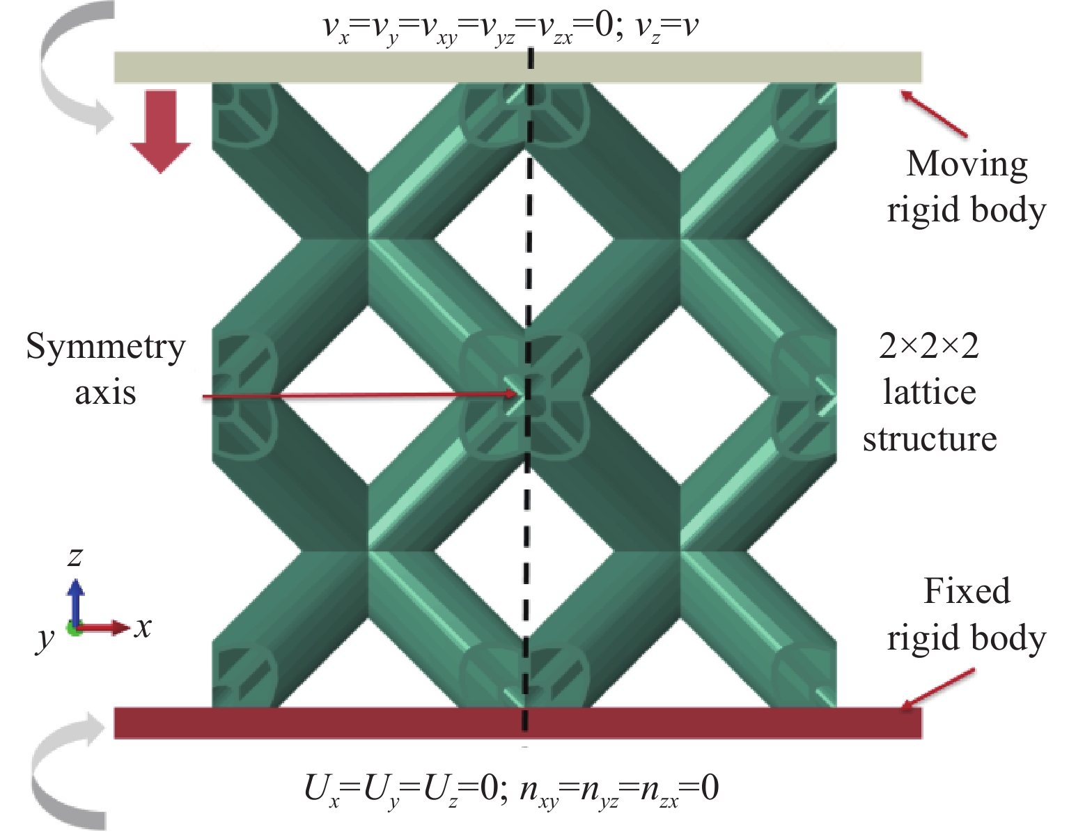
图 3 晶格结构准静态压缩有限元模型
Figure 3. Quasi-static compression finite elementmodel of lattice structure

图 6 验证试样及其实验和数值模拟对比
Figure 6. Validated samples and comparison of the experiments and numerical simulations

图 7 4种相对密度下晶格结构的应力-应变曲线
Figure 7. Stress-strain curves of lattice structure under four relative densities

图 8 相对密度为22%的4种结构的能量吸收曲线
Figure 8. Energy absorption curves of four structures with a relative density of 22%

图 11 Ⅰ型晶格结构变形模式和应力云图
Figure 11. The deformation mode and strain nephogramof the typeⅠlattice structure
表 1 晶格结构的物理参数
Table 1. Physical parameters of the lattice structure
Lattice
structureRelative
density/%Diameter/mm Cross-sectional
area/mm2Thickness/mm Minimum
thickness/mmOriginal structure 13 1.66 15 1.81 19 2.08 22 2.25 Hollow
structure13 26.56 0.35 15 30.88 0.41 19 38.56 0.54 22 43.58 0.64 Type Ⅰ
structure13 24.07 0.06 15 27.80 0.07 19 36.64 0.10 22 41.92 0.12 Type Ⅱ
structure13 23.84 0.10 15 28.22 0.13 19 36.13 0.17 22 41.41 0.20  下载: 导出CSV
表 2 晶格结构在0 < ε < 0.4范围内的能量吸收和比吸能
Table 2. Energy absorption and specific energy absorption of lattice structure at 0 < ε < 0.4
Lattice structure Mass/g EA/MJ ESA/(MJ·g–1) Original structure 7.98 48.13 6.03 9.53 54.39 5.71 12.21 68.51 5.62 13.98 81.72 5.85 Hollow structure 8.14 78.13 9.60 9.55 86.58 9.07 12.23 105.68 8.64 14.04 114.65 8.17 Type I structure 8.14 78.62 9.66 9.40 88.14 9.38 Type I structure 12.39 97.83 7.90 14.16 105.64 7.46 Type Ⅱ structure 8.04 79.21 9.85 9.58 87.29 9.11 12.26 99.52 8.12 14.04 103.16 7.35
下载: 导出CSV
-
[1] CAO X F, DUAN S Y, LIANG J, et al. Mechanical properties of an improved 3D-printed rhombic dodecahedron stainless steel lattice structure of variable cross section [J]. International Journal of Mechanical Sciences, 2018, 145: 53–63. doi: 10.1016/j.ijmecsci.2018.07.006 [2] BAI L, YI C Y, CHEN X H, et al. Effective design of the graded strut of BCC lattice structure for improving mechanical properties [J]. Materials, 2019, 12: 2192. doi: 10.3390/ma12132192 [3] LI P F. Simulating the dynamic deformation behaviour of selective laser melted stainless steel microlattice structures [J]. 2016. [4] TSOPANOS S, MINES R A W, MCKOWN S, et al. The influence of processing parameters on the mechanical properties of selectively laser melted stainless steel microlattice structures [J]. Journal of Manufacturing Science and Engineering, 2010, 132(4): 041011. doi: 10.1115/1.4001743 [5] JIN N, WANG F C, WANG Y W, et al. Failure and energy absorption characteristics of four lattice structures under dynamic loading [J]. Materials & Design, 2019, 169: 107655. doi: 10.1016/j.matdes.2019.107655 [6] 郝美荣. 菠萝叶纤维增强点阵圆筒结构的平压性能研究 [D]. 哈尔滨: 东北林业大学, 2017.HAO M R. Compression performance of pineapple leaf fiber reinforced lattice cylinder [D]. Harbin: Northeast Forestry University, 2017. [7] TSANG H H, RAZA S. Impact energy absorption of bio-inspired tubular sections with structural hierarchy [J]. Composite Structures, 2018, 195: 199–210. doi: 10.1016/j.compstruct.2018.04.057 [8] ZOU M, XU S C, WEI C G, et al. A bionic method for the crashworthiness design of thin-walled structures inspired by bamboo [J]. Thin-Walled Structures, 2016, 101: 222–230. doi: 10.1016/j.tws.2015.12.023 [9] LIU Q, MA J B, HE Z H, et al. Energy absorption of bio-inspired multi-cell CFRP and aluminum square tubes [J]. Composites Part B: Engineering, 2017, 121: 134–144. doi: 10.1016/j.compositesb.2017.03.034 [10] TAO Y, LI W G, WEI K, et al. Mechanical properties and energy absorption of 3D printed square hierarchical honeycombs under in-plane axial compression [J]. Composites Part B: Engineering, 2019, 176: 107219. doi: 10.1016/j.compositesb.2019.107219 [11] 魏灿刚. 仿竹结构薄壁管的耐撞性设计和分析 [D]. 长春: 吉林大学, 2014.WEI C G. Crashworthiness bionic design and analysis of thin-walled tube inspired by bamboo structure [D]. Changchun: Jilin University, 2014. [12] HABIB F N, IOVENITTI P, MASOOD S H, et al. Fabrication of polymeric lattice structures for optimum energy absorption using Multi Jet Fusion technology [J]. Materials & Design, 2018, 155: 86–98. doi: 10.1016/j.matdes.2018.05.059 [13] MUELLER J, SHEA K. Stepwise graded struts for maximizing energy absorption in lattices [J]. Extreme Mechanics Letters, 2018, 25: 7–15. doi: 10.1016/j.eml.2018.10.006 -

 下载:
下载:


计量
- 文章访问数: 6993
- HTML全文浏览量: 3218
- PDF下载量: 77
