


Dimensionless Formulae for Punching Shear Strengthof Reinforced Concrete Slabs
doi: 10.11858/gywlxb.2016.04.005
-
Abstract: Punching shear plays a very important role in assessing the load carrying capacities of connections between slabs and columns or slabs loaded by flat-faced punches, especially in the safety calculation and assessment of containment structures in nuclear power plants.For many years this has been examined by researchers and the influences of the span-to-depth ratio on punching shear strengths are often neglected, and all the equations employed in the current codes are dimensionally inconsistent.We proposed a dimensionless new empirical equation to predict the punching shear strengths of reinforced concrete circular slabs without shear reinforcement which are loaded quasi-statically by flat-faced circular indentors.In the present formulation, we took into consideration various effects such as rebar quantity, rebar spacing and span-to-depth ratio.It is shown that the present equation is in good correlation with available experimental results.It is also shown that the present equation is applicable to square punches as well as square slabs.
-
1. Introduction
Reinforced concrete structures are widely used in various engineering projects.However, the catastrophic nature of the failure exhibited at the connections between slabs and columns or slabs loaded by flat-ended punches has been of major concern to civil and safety engineers[1-4].The punching shear behavior of the connections between slabs and columns or slabs loaded quasi-statically by flat-faced punches has been investigated by researchers for many years and various empirical equations have been proposed to predict the punching shear strengths of concrete slabs loaded by square or circular indentors.
The widely used empirical equations are ACI 318-11[5], Euro-code 2 (2004)[6], JSCE (Japan Society of Civil Engineers) (2002)[7] and BS 8110-97[8].However, these equations were derived based on the experimental data obtained for a limited range of parameters examined which were different from each other.In the majority of empirical equations, the punching resistances were simply taken to be the product of nominal shear strength and area of an assumed failure surface.In other words, the failure load was calculated by assuming that the shear stress is uniformly distributed on a cylindrical surface, with a 'control perimeter'.The gap between the assumed punching shear failure surface and the punch surface used in the formulation of the empirical equations varies from 0.5 to 2.0 times the effective depths of concrete slabs examined.However, the actual failure surface is not cylindrical, as observed from experiments.All the empirical equations have neglected the influences of rebar spacing on the punching shear strength.
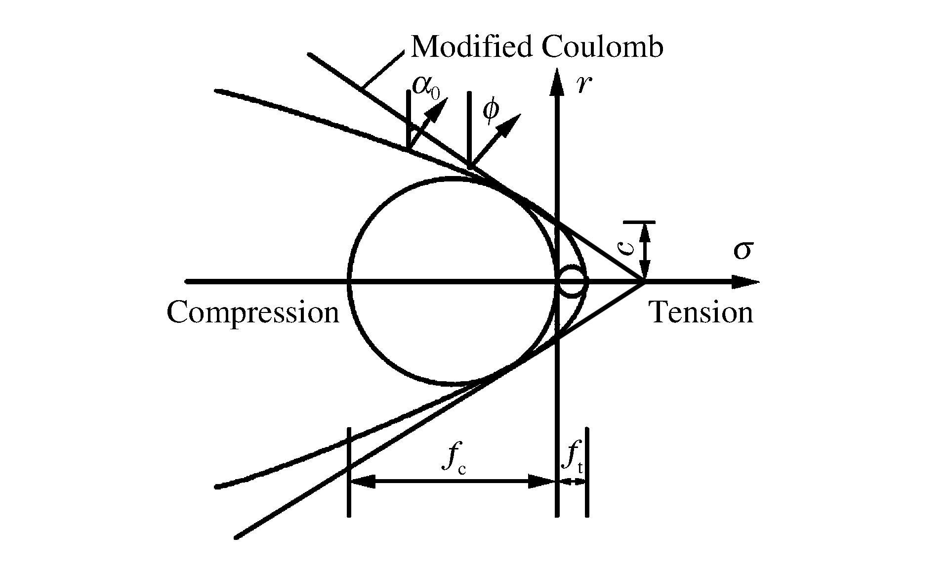
Kinnunen and Nylander[9] developed the first failure mechanism model to compute the punching strength based on 61 tests on circular slabs with circular column stubs.They derived the expression of punching shear strength by assuming that the rigid segments outside the punching cone were carried by a triaxially compressed truncated conical shell starting from the column to the root of the punching crack.Muttoni[10] proposed the critical shear crack theory (SCCT) for the punching shear strength of reinforced concrete slabs without shear reinforcement based on parameter rotation.It was demonstrated that the span-to-depth ratio has an effect on the punching shear strength.Braestrup et al. [11] proposed a rigid-plastic model for the analysis of punching shear failure in concrete slabs.The failure criterion by cracking was based on the Modified Coloumb's law, viz. τ-σtanΦ-c=0(see Fig. 1), where τ is the shear stress, σ the normal stress, c the cohesive strength and the internal friction angle of the concrete related to its compressive strength.The tensile strength ft was set at a very low value, i.e., ft=fc/400, where fc is the compressive strength.The ultimate load Pu was calculated by comparing the fracture energy of the conical shell with the work done by applied loads.
 Figure 1. Failure criterion for concrete (α0 is theangle of tangent to yield line with vertical)
Jiang and Shen[12] derived an equation to evaluate the load-carrying capacity of concrete slabs in punching shear by introducing a parabolic Coulomb-Mohr intrinsic curve reflecting the convexity of failure envelope.As can be seen from Fig. 1, the parabola gives the relationship between shear stress τ and normal stress σ on the yield surface.However, in the theoretical model an effective compressive strength of concrete was used instead of its unconfined compressive strength measured by standard tests.Later on, Lionello[13] employed the principle of engineering plasticity to construct a model to predict the load-carrying capacity of concrete slabs by simplifying the punch load as a uniformly distributed local load at the centre.It has to be mentioned here that the effects of rebar quantity and rebar spacing were not taken into account in the above two models.
In this paper, we propose a new empirical equation to predict the punching shear strengths of reinforced concrete slabs loaded quasi-statically by flat-faced circular indentors.The equation is presented in non-dimensional form and accounts for the effects of rebar quantity and rebar spacing on the punching shear strength.The influence of the span-to-depth ratio on the punching shear strength is also catered for in the present formulation.The new empirical equation is compared with available experimental data.Furthermore, it is also compared with some existing design codes, followed by discussion.
2. An Overview of the Existing Desigh Codes
2.1 ACI 318-11 Code
In ACI 318-11 code, the punching shear strength τs for slabs without shear reinforcement is taken as the minimum of the following 3 limits, viz.
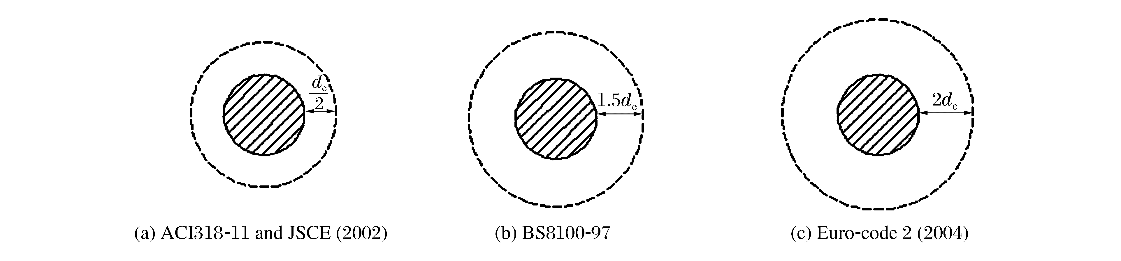
τs=min{0.083λ(2+4βc)√f′c,0.083λ(2+αsdeb0)√f′c,0.33λ√f′c} (1) where λ=1.0 for normal weight concrete, λ=0.85 for sand-light weight concrete and λ=0.75 for light concrete; fc′ is the unconfined compressive strength of concrete in MPa, the value of √f′c imposed is limited to 8.3MPa1/2; βc is the ratio of the maximum to the minimum dimensions of the critical section; b0 is the perimeter of the critical section; αs is a scale factor based on the location of the critical section, and αs=40 for interior columns.The ACI 318-11 code assumes that the control perimeter is at a 0.5de distance from the edge of load area or the periphery of the punch-slab interface with de being the effective depth of the reinforced concrete slab (see Fig. 2).The influence of reinforcement is not considered in the ACI 318-11 code.
 Figure 2. Control perimeters of concrete slabs loaded by circular column as specified inACI 318-11, Euro-code 2, JSCE and BS8110-97
2.2 Euro-Code 2 (2004)
In Euro-code 2 (2004), which takes into account the influence of acrit/de (acrit is the distance from the column face to the control perimeter considered), the punch shear strength τs can be written as
τs=Crd,cξ(100ζfck)132deacrit (2) where Crd, c=0.18/γc is an empirical factor derived from regression analysis and γc=1.5 for concrete materials, fck is the characteristic compressive strength of concrete in MPa, the size factor of the effective depth ξ=1+√200/de is limited to the maximum value 2.0, the flexural reinforcement ratio ζ is less than 2%.The critical perimeter is at a distance 2de from the edge of load area, as shown in Fig. 2.All the dimensions are in mm.It should be mentioned here that in the practical engineering Eq.(2) must satisfy the following expression
τs≥τmin2deacrit (3) where τmin=0.035ξ3/2√fck(MPa).
2.3 The JSCE (2002)
The Japan Society of Civil Engineers equation for predicting the punching shear strength of reinforced concrete slabs is given as follows
{τs=βdβpβrfpcd/rbfpcd=0.2√f′cβd=4√1000/deβp=3√100ρβr=1+(1+0.25b/de)−1 (4) where rb=1.3,b is the perimeter of column or loading plate andρis the concrete density; fpcd , βd and βp are limited to 1.2MPa, 1.5 and 1.5, respectively.The critical section is located at a distance of de/2 from the edge of the load area, as shown in Fig. 2.
2.4 The BS 8110-97 Code
In the BS 8110-97 code the punch shear strength τs can be expressed as
τs=0.793√100ζ(fcu/25)4√400/de (5) where (400/de)1/4 can be viewed as a size-effect coefficient , fcu is the cube compressive strength in MPa and can be taken as fcu=1.25f′c. The control section is 1.5 de from the edge of the load area (see Fig. 2).
3. Formulation of a New Empirical Equation
Some of the existing design codes briefly mentioned above in the previous section are the simplest and most reliable approaches so far, but their failure surfaces are not at all similar to failure surfaces obtained in numerous tests.According to the experimental observations made by Hallgren et al. [14], the failure surfaces are similar to those described in the works of Braestrup et al.[11] and Jiang et al. [12].However, due to the complexity of the punching shear of concrete slabs, the models proposed in Ref.[11-12] did not consider the effect of reinforcement.Moreover, all the formulae presented in the previous section are not even dimensionally consistent, which means the accuracy and the range of their applicability are largely compromised.To this end, we suggest a new empirical formula for the punching shear strength of reinforced concrete slabs loaded by circular punches which caters for various effects while being dimensionally consistent.
3.1 A New Empirical Formula
The punching shear of concrete slabs is influenced by a great number of factors such as the concrete strength, the type and amount of flexural reinforcement, dimensions and other characteristics.In particular, it is difficult to determine the stress state of failure surfaces since shear and normal stresses on the failure surface are interconnected and influenced by the aggregate size and reinforcement.Yankelevsky and Leibowitz[15] analyzed the test results for punch shear of concrete slabs reported by Bazant and Cao[16] by assuming the distribution of shear and normal stresses along the failure surfaces.Their study shows that the normal stress on the failure surface, as compared with the shear stress, is small and its maximum occurs in the compression zone with a small sloping angle.Therefore, the contribution of normal stress to punching shear is negligible.
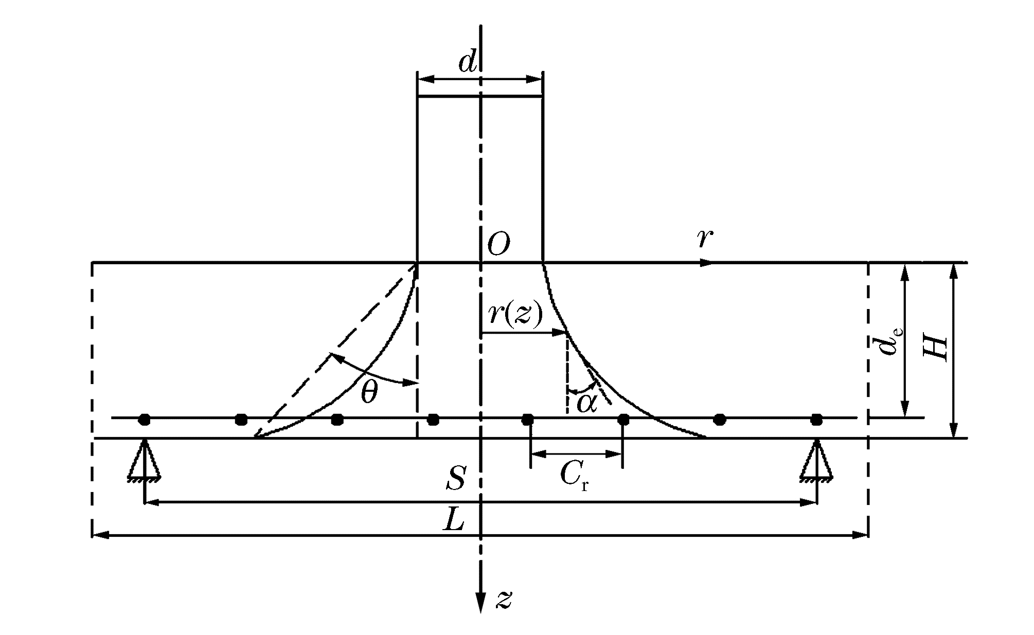
When the applied load reaches the load bearing capacity of a reinforced concrete slab, cone cracking occurs and a plug is formed as shown schematically in Fig. 3.Hence, we have
 Figure 3. Schematic showing punching shear failure(L is the side length of a square reinforcedconcrete slab)
Pu=∫H0(τscosα)×dA=∫H0(τscosα)×2πr(z)dzcosα=∫H02πτsr(z)dz (6) where Pu is the punching load, r(z)the diameter of the plug at a depth of z (see Fig. 3), and α the angle between the vertical line and the tangential direction.The punching shear strength (τs) is assumed to be distributed uniformly over the shear area of the cone plug surface and is evaluated without the influence of any additional bending load effects, similar to the punching shear strength considered in the studied codes.It is further assumed that the punching shear strength (τs) can be expressed in the following non-dimensional form, viz.
τsf′c=κη(SH)β(Hd)γ (7) where H is the total thickness of the reinforced concrete slab, S is the span of the reinforced concrete slab and is defined to be the diameter of axisymmetric slab to tie in with the test specimen that are simply supported on a ring, d is the punch diameter, and κ , β and γ are empirical constants. η is a parameter which accounts for the influences of rebar quantity and rebar spacing on the punching shear strength and, to a first approximation, may be written as[17]
η={38dCrrt+0.5ifdCr<√ddr38√ddrrt+0.5ifdCr≥√ddr (8) where rt is the total flexural reinforcement and is defined as rt=πdr2/4HCr , Cr is the rebar spacing and dr the rebar diameter.
The profile of the formed shear plug can be expressed by the following equation[12]
r=C2eC1z (9) where C1 and C2 can be determined by the following boundary conditions, i.e., r(z=0)=d/2 and r(z=H)=d/2+Htanθ (θ is the cone slope angle as defined in Fig. 3), which gives
C1=1Hlnd+2HtanθdandC2=d2 (10) Substituting Eq.(9) into Eq.(6) yields
Pu=2πτs∫H0C2eC1zdz=2πτsC2eC1H−1C1=2πτsH2tanθln(1+2Htanθ/d) (11) after using Eq.(10) for C1 and C2 .The cone slope angle (θ) has been observed experimentally to lie between 55° and 70°[13, 18].In the present paper, θ is taken to be θ=65°for S/H≥tan65°=2.145and θ=arctan[(S-d)/2H]for S/H < 2.145.
3.2 Determination of κ, β and γ
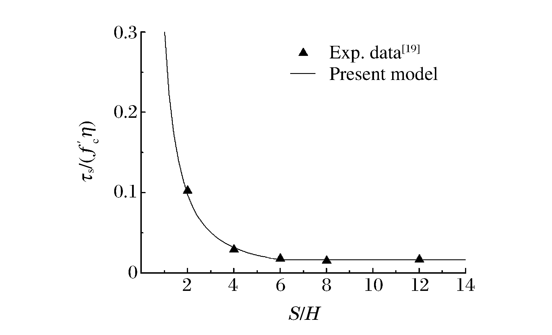
Lovrovich and Mclean[19] conducted an experimental investigation into the punching shear behavior of reinforced concrete slabs with varying span-to-depth ratios.The ratio of slab thickness to column (punch) diameter was kept constant and so was the flexural reinforcement of the reinforced concrete slabs examined, thus the punching shear strengths of the reinforced concrete slabs were affected only by the span-to-depth ratio.The thickness of all the reinforced concrete slabs was 101.6mm and the diameter of the column (punch) was 101.6mm, hence, H/d=1.The spans of the reinforced concrete slabs were 203.2, 406.4, 609.6, 812.8 and 1219.2mm, which gave the span-to-depth ratios of 2, 4, 6, 8 and 12, respectively.It is easy to show that η=2.78 by substituting the values of various parameters for the reinforced concrete slabs examined in Ref.[19] into Eq.(8).
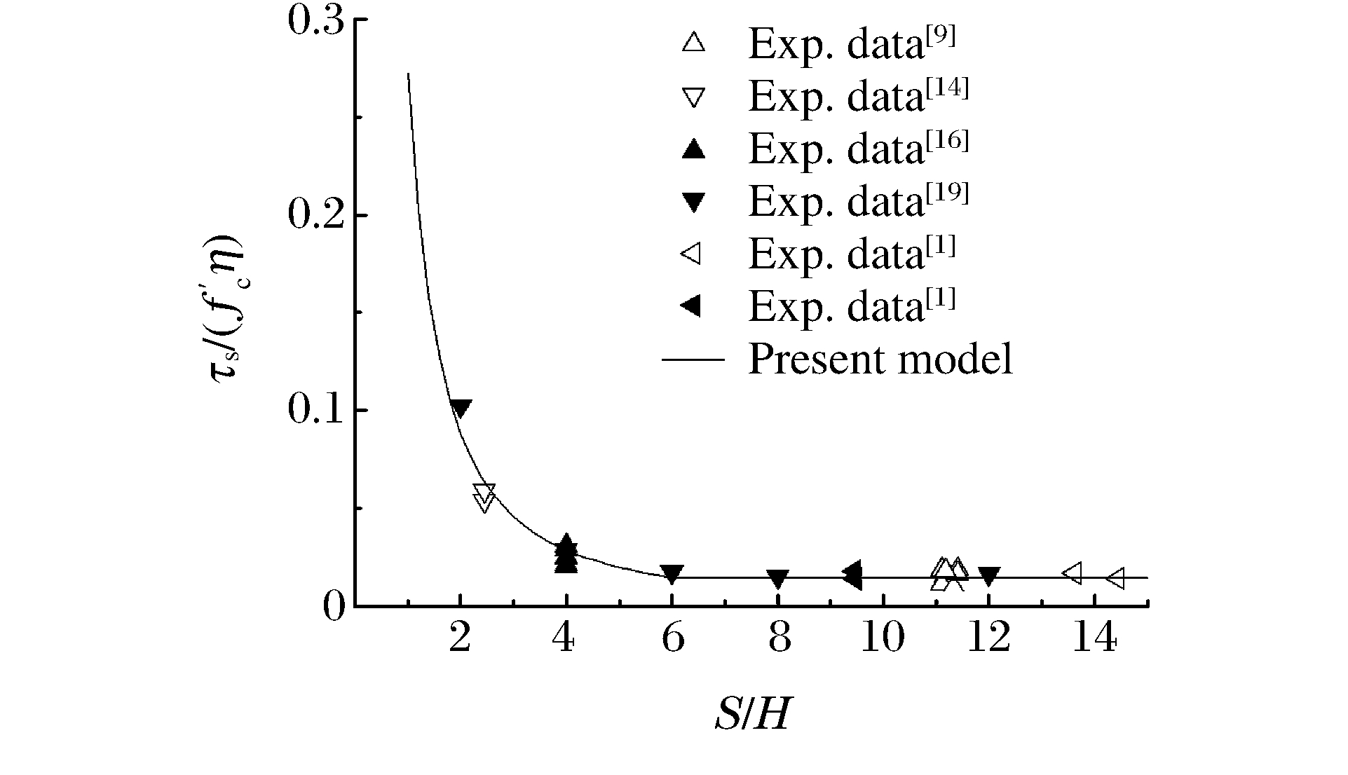
The experimental data obtained by Lovrovich and Mclean[19] are presented graphically in Fig. 4 in non-dimensional form and it can be seen from Fig. 4 that the experimental results can be divided into two groups, one for S/H ≤6 where the punch shear strength is a function of the span-to-depth ratio and the other for S/H > 6 where the punch shear strength is independent of the span-to-depth ratio.By using the experimental data for S/H=2, 4 and 6 and the least square method, it is found that κ=0.272 and β=-1.62.Hence, Eq.(7) can be recast into the following form
τsf′c={0.272η(SH)−1.62(Hd)γforSH≤60.015η(Hd)γforSH>6 (12)  Figure 4. Dimensionless punching shear strengthvs. span-to-depth ratio
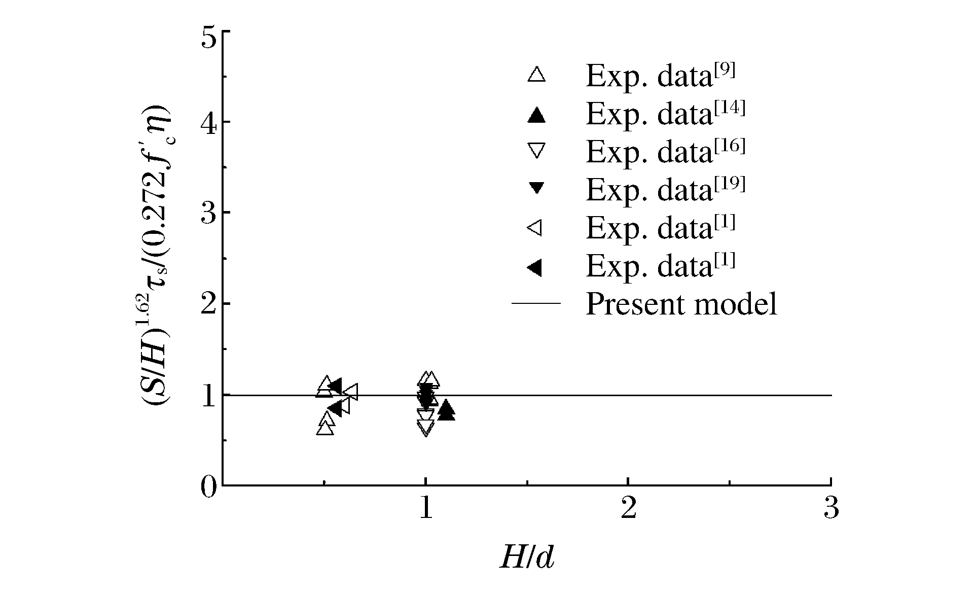
There still remains one parameter (γ) in Eq.(12) which needs to be determined.Fig. 5 shows variation of experimentally obtained punch shear strength with the ratio of slab thickness to column (punch) diameter.As can be seen from the limited experimental data presented in Fig. 5, the punch shear strength is nearly independent of the ratio of slab thickness to column (punch) diameter although the experimental results are somehow scattered.Hence, it is reasonable to assume that γ in Eq.(12) can be taken to be zero.Thus, Eq.(12) can be rewritten as
τsf′c={0.272η(SH)−1.62forSH≤60.015ηforSH>6 (13)  Figure 5. Dimensionless punching shear strengthvs. slab thickness to column diameter ratio
where η is estimated by Eq.(8).It is interesting to note from Eq.(13) that punch shear strength is influenced by the span-to-depth ratio (S/H) only when it is small (here it is less than 6), and for larger span-to-depth ratio the punch shear strength is only related to the unconfined compressive strength (f′c) and the configuration of the bending reinforcement in terms of the parameter η .
4. Comparisons and Discussion
The empirical equation proposed in Section 3 is compared with available experimental data in Fig. 6, from which it is obvious that the present empirical equation is in good agreement with the experimental results.
 Figure 6. Comparison of the present empirical model(Eq.(13)) with available experimental data
Comparisons are also made in Table 1 between the experimentally observed ultimate load capacities (Pu) and the predicted values (Pm) from the present empirical model (Eq.(11) and Eq.(13)) and the empirical formulae adopted in various codes described in Section 2.Table 1 indicates that the present empirical model (Eq.(11) and Eq.(13)) is in good agreement with the experimental observations.
Table 1. Comparisons of various formulae with available experimental resultsExp.No. L/(mm) S/(mm) H/(mm) de/(mm) d/(mm) fc′/(MPa) ζ/(%) Pu/(kN)(Exp.) Pu/Pm Ref. ACI318-11 BS8110-97 JSCE(2002) Euro-code2 (2004) Eq.(11) IA15b-7 1840 1710 153 124 150 28.0 2.03 247.2 1.33 1.25 0.88 0.84 1.03 IA15b-8 1840 1710 153 121 150 27.5 2.03 247.2 1.39 1.30 0.92 0.88 1.05 IA15b-9 1840 1710 150 117 150 25.5 2.18 274.6 1.68 1.51 1.08 1.02 1.27 IA15b-10 1840 1710 150 117 150 25.5 2.18 274.6 1.68 1.51 1.08 1.02 1.27 IA15c-11 1840 1710 153 121 150 31.5 2.16 333.5 1.75 1.64 1.14 1.11 1.24 [9] IA15c-12 1840 1710 154 122 150 30.4 2.16 331.5 1.75 1.63 1.14 1.10 1.27 IA30a-22 1840 1710 154 128 300 27.8 1.01 254.0 0.85 1.08 0.81 0.85 0.79 IA30a-23 1840 1710 151 125 300 26.7 1.04 207.9 0.73 0.91 0.68 0.72 0.68 IA30e-34 1840 1710 150 120 300 26.9 1.00 331.5 1.22 1.54 1.15 1.22 1.14 IA30e-35 1840 1710 153 122 300 24.6 0.98 331.5 1.25 1.57 1.19 1.24 1.23 2A 127 101.6 25.4 127 21.437 47.7 3.36 22.46 3.13 1.75 1.13 0.99 0.71 2B 254 203.2 50.8 254 42.545 47.7 3.07 78.73 2.77 1.90 1.22 1.16 0.88 2C 508 406.4 101.6 508 85.09 47.7 3.07 309.6 2.72 2.22 1.43 1.42 0.86 [16] 3A 127 101.6 25.4 127 21.437 45.3 2.74 16.32 2.33 1.38 0.90 0.78 0.75 3B 254 203.2 50.8 254 42.545 45.3 2.43 60.63 2.19 1.61 1.05 0.98 1.08 3C 508 406.4 101.6 508 85.09 45.3 2.43 228.9 2.07 1.80 1.17 1.16 1.02 F1 203.2 200 101.6 83 101.6 39.3 1.75 479.5 4.86 4.60 3.07 1.97 1.16 F2 406.4 400 101.6 83 101.6 39.3 1.75 204.2 2.07 1.96 1.30 1.26 1.01 F3 609.6 600 101.6 83 101.6 39.3 1.75 149.0 1.51 1.43 0.95 0.94 1.20 [19] F4 812.8 800 101.6 83 101.6 39.3 1.75 129.0 1.31 1.24 0.83 0.82 1.04 F5 1500 1200 101.6 83 101.6 39.3 1.75 138.8 1.41 1.33 0.89 0.88 1.12 S12 960 674 275 250 250 28.2 0.42 1049 1.60 2.97 2.07 1.53 0.85 [14] S13 960 674 275 250 250 19.8 0.42 803 1.45 2.53 1.87 1.30 0.93 9-1 2750 2600 180 143 300 37.3 1.48 628 1.57 1.88 1.32 1.44 0.97 [1] 9-2 2750 2600 191 171 300 28.5 1.18 626 1.40 1.79 1.29 1.31 1.14 12-1 2900 2650 280 240 500 29.3 1.3 1662 1.67 2.28 1.66 1.75 0.94 [1] 12-2 1400 1200 127 109 226 33.3 1.2 326 1.66 1.95 1.39 1.48 1.21 S1 850 600 275 242 250 39.8 0.40 1363 1.75 3.49 2.30 1.68 0.81 S2 850 600 277 243 250 28.4 0.40 1015 1.53 2.90 2.02 1.39 0.83 S3 850 600 278 250 250 29.8 0.39 1008 1.43 2.75 1.90 1.30 0.78 [14](Squareslabs) S7 850 600 277 246 250 14.4 0.40 622 1.30 2.19 1.71 1.04 1.01 S8 850 600 277 245 250 31.4 0.25 915 1.30 2.92 2.00 1.39 1.19 S9 850 600 277 244 250 25.5 0.40 904 1.43 2.66 1.89 1.27 0.83 S11 850 600 274 235 250 28.2 0.41 1190 1.90 3.53 2.47 1.71 1.00 S14 850 600 273 240 250 21.4 0.41 1100 1.95 3.48 2.54 1.67 1.23 | Show Table DownLoad:
CSV
DownLoad:
CSV
Table 2 provides the mean value, the standard deviation, the coefficient of variation, and confidence intervals of the ratios of ultimate load capacities (Pu) and the loads estimated by various codes and the present empirical model (Pm).The mean value of Pu/Pm given by Eq.(11) is close to unity, meaning that the estimated values are close to experimental results.The coefficients of variation in BS8110-97, JSCE (2002) are close to 40% and those in ACI 318-11 and Euro-code (2004) are close to 45% and 26.50%, respectively.The coefficient of variation in Euro-code (2004) is considerably lower than those in BS8110-97, JSCE (2002) and ACI 318-11, this is partly because Euro-code (2004) has taken into account the effect of the span-to-depth ratio on the punching shear strength.The 95% confidence intervals and the standard error are also given in Table 2.As can be seen from Table 2, the present model has a standard error of 0.07 while ACI 318-11, BS8110-97, JSCE (2002) and Euro-code (2004) have a standard error of 0.32, 0.28, 0.19 and 0.12, respectively.Hence, conclusion can be drawn that the present model has better estimates of the punching load compared with the existing empirical formulae regarding the statistical method.
Table 2. Comparisons of various formulae through the statistical methodEquation Pu/Pm Mean Standard deviation Coefficient of variation 95% confidence interval ACI 318-11 1.83 0.82 44.90 1.83±0.32 BS8110-97 1.80 0.72 39.78 1.80±0.28 JSCE (2002) 1.25 0.48 38.72 1.25±0.19 Euro-code 2 (2004) 1.15 0.31 26.50 1.15±0.12 Eq.(11) 1.03 0.18 17.45 1.03±0.07 | Show TableDownLoad:
CSV
To a first approximation, the present empirical equations can also be applied to square reinforced concrete slabs loaded by circular columns or punches on the basis of the same slab area.Thus, we have
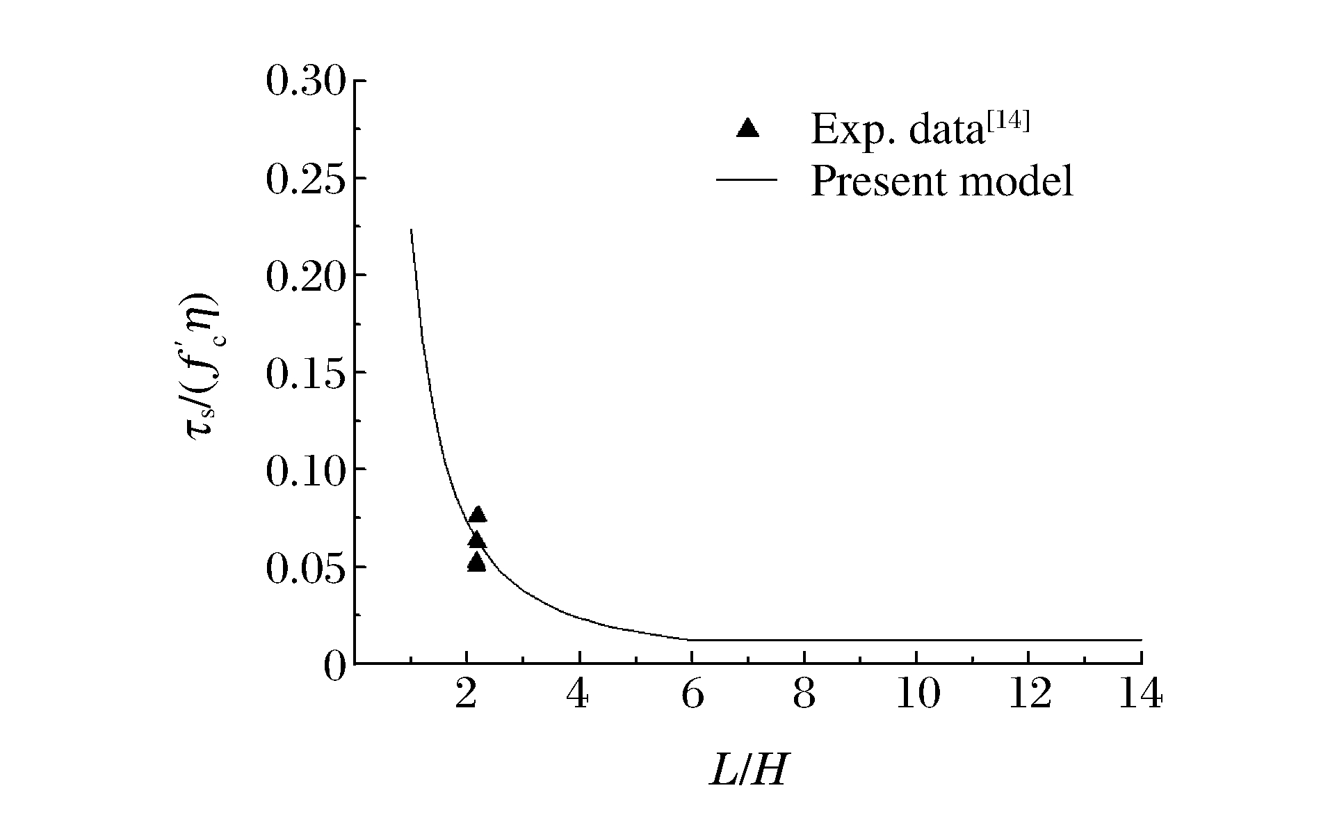
L2=πS24 (14) where L is the side length of a square reinforced concrete slab and S the span or diameter of an equivalent circular plate.Fig. 7 shows the comparison of the present empirical model with the experimental results for square reinforced concrete slabs loaded by circular punches. The square slabs examined in Ref.[14] had a side length of 850mm and a thickness of 275mm.The test area is 600mm×600mm which gives an equivalent span or diameter of 677mm.As can be seen from Fig. 7 that good agreement is obtained between the empirical model and the experimental results.
 Figure 7. Comparison of the present empiricalmodel with the experimental results forsquare reinforced concrete slabsloaded by a circular punch
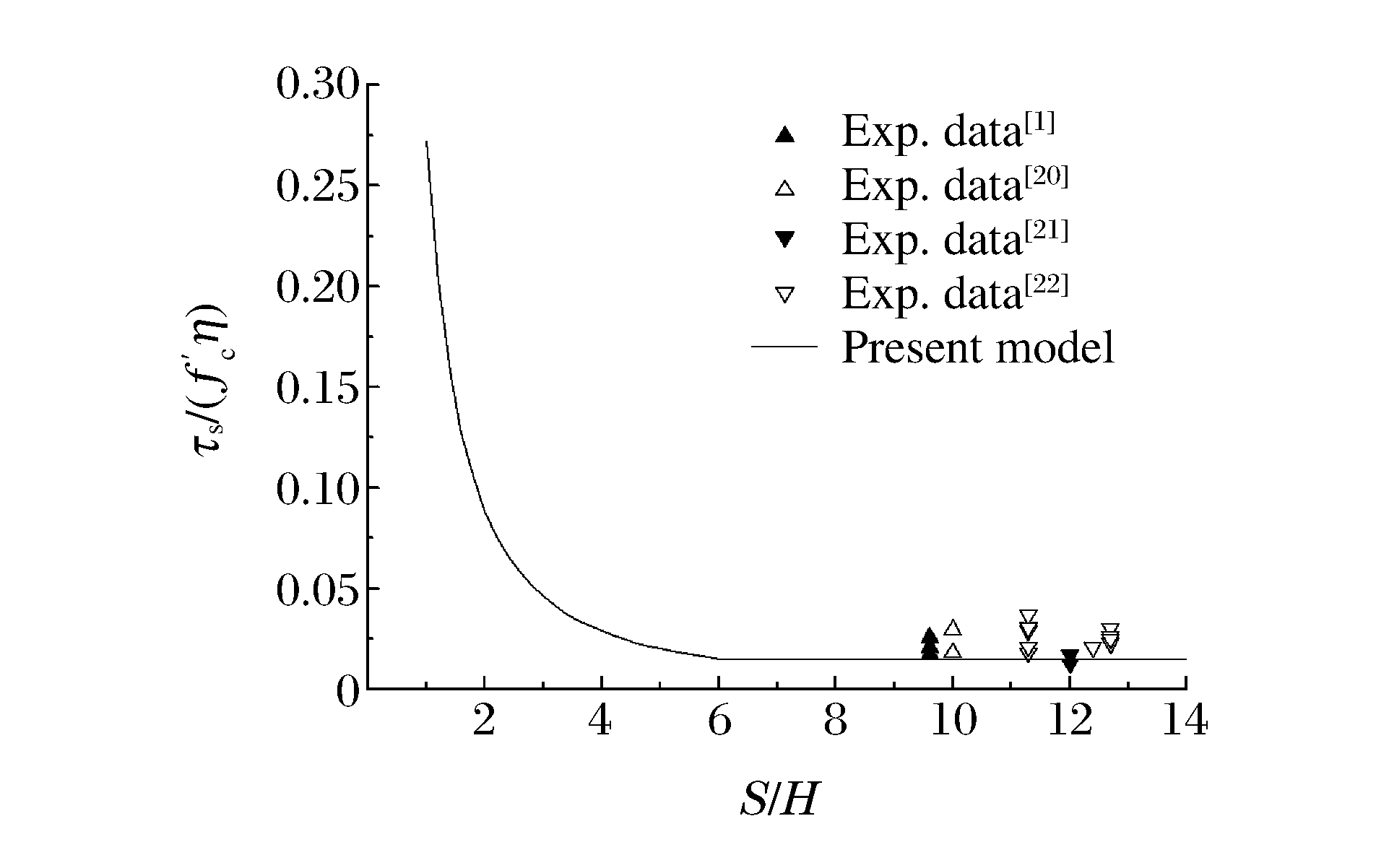
In order to make assessment about the punching shear capacity of a reinforced concrete slab loaded by a square column as compared with a circular column of the same circumferential length, Fig. 8 shows the comparison of the present empirical model with the experimental results for the reinforced concrete slabs loaded by square columns as reported in Ref.[1, 20-22]. It can be seen from Fig. 8 that the punching shear capacities of reinforced concrete slabs loaded by square columns are slightly higher than those loaded by circular columns with the same circumferential lengths.In other words, a circular column is more dangerous compared with a square column based on the same circumferential length or area.
 Figure 8. Comparison of the present empiricalmodel with the experimental resultsfor the reinforced concrete slabsloaded by a square punch
5. Conclusions
A dimensionless new empirical equation has been proposed in the present paper to predict the punching shear strengths of reinforced concrete slabs loaded quasi-statically by flat-faced circular columns or punches.Various effects such as rebar quantity, rebar spacing and span-to-depth ratio are taken into consideration in the present formulation.
It is shown that the present empirical equation is in good agreement with available experimental results, and that the present equation is advantageous over the existing empirical formulae for circular reinforced concrete slabs loaded by circular punches.
-

Figure 1. Failure criterion for concrete (α0 is theangle of tangent to yield line with vertical)

Figure 2. Control perimeters of concrete slabs loaded by circular column as specified inACI 318-11, Euro-code 2, JSCE and BS8110-97

Figure 3. Schematic showing punching shear failure(L is the side length of a square reinforcedconcrete slab)

Figure 5. Dimensionless punching shear strengthvs. slab thickness to column diameter ratio

Figure 6. Comparison of the present empirical model(Eq.(13)) with available experimental data

Figure 7. Comparison of the present empiricalmodel with the experimental results forsquare reinforced concrete slabsloaded by a circular punch

Figure 8. Comparison of the present empiricalmodel with the experimental resultsfor the reinforced concrete slabsloaded by a square punch
Table 1. Comparisons of various formulae with available experimental results
Exp.No. L/(mm) S/(mm) H/(mm) de/(mm) d/(mm) fc′/(MPa) ζ/(%) Pu/(kN)(Exp.) Pu/Pm Ref. ACI318-11 BS8110-97 JSCE(2002) Euro-code2 (2004) Eq.(11) IA15b-7 1840 1710 153 124 150 28.0 2.03 247.2 1.33 1.25 0.88 0.84 1.03 IA15b-8 1840 1710 153 121 150 27.5 2.03 247.2 1.39 1.30 0.92 0.88 1.05 IA15b-9 1840 1710 150 117 150 25.5 2.18 274.6 1.68 1.51 1.08 1.02 1.27 IA15b-10 1840 1710 150 117 150 25.5 2.18 274.6 1.68 1.51 1.08 1.02 1.27 IA15c-11 1840 1710 153 121 150 31.5 2.16 333.5 1.75 1.64 1.14 1.11 1.24 [9] IA15c-12 1840 1710 154 122 150 30.4 2.16 331.5 1.75 1.63 1.14 1.10 1.27 IA30a-22 1840 1710 154 128 300 27.8 1.01 254.0 0.85 1.08 0.81 0.85 0.79 IA30a-23 1840 1710 151 125 300 26.7 1.04 207.9 0.73 0.91 0.68 0.72 0.68 IA30e-34 1840 1710 150 120 300 26.9 1.00 331.5 1.22 1.54 1.15 1.22 1.14 IA30e-35 1840 1710 153 122 300 24.6 0.98 331.5 1.25 1.57 1.19 1.24 1.23 2A 127 101.6 25.4 127 21.437 47.7 3.36 22.46 3.13 1.75 1.13 0.99 0.71 2B 254 203.2 50.8 254 42.545 47.7 3.07 78.73 2.77 1.90 1.22 1.16 0.88 2C 508 406.4 101.6 508 85.09 47.7 3.07 309.6 2.72 2.22 1.43 1.42 0.86 [16] 3A 127 101.6 25.4 127 21.437 45.3 2.74 16.32 2.33 1.38 0.90 0.78 0.75 3B 254 203.2 50.8 254 42.545 45.3 2.43 60.63 2.19 1.61 1.05 0.98 1.08 3C 508 406.4 101.6 508 85.09 45.3 2.43 228.9 2.07 1.80 1.17 1.16 1.02 F1 203.2 200 101.6 83 101.6 39.3 1.75 479.5 4.86 4.60 3.07 1.97 1.16 F2 406.4 400 101.6 83 101.6 39.3 1.75 204.2 2.07 1.96 1.30 1.26 1.01 F3 609.6 600 101.6 83 101.6 39.3 1.75 149.0 1.51 1.43 0.95 0.94 1.20 [19] F4 812.8 800 101.6 83 101.6 39.3 1.75 129.0 1.31 1.24 0.83 0.82 1.04 F5 1500 1200 101.6 83 101.6 39.3 1.75 138.8 1.41 1.33 0.89 0.88 1.12 S12 960 674 275 250 250 28.2 0.42 1049 1.60 2.97 2.07 1.53 0.85 [14] S13 960 674 275 250 250 19.8 0.42 803 1.45 2.53 1.87 1.30 0.93 9-1 2750 2600 180 143 300 37.3 1.48 628 1.57 1.88 1.32 1.44 0.97 [1] 9-2 2750 2600 191 171 300 28.5 1.18 626 1.40 1.79 1.29 1.31 1.14 12-1 2900 2650 280 240 500 29.3 1.3 1662 1.67 2.28 1.66 1.75 0.94 [1] 12-2 1400 1200 127 109 226 33.3 1.2 326 1.66 1.95 1.39 1.48 1.21 S1 850 600 275 242 250 39.8 0.40 1363 1.75 3.49 2.30 1.68 0.81 S2 850 600 277 243 250 28.4 0.40 1015 1.53 2.90 2.02 1.39 0.83 S3 850 600 278 250 250 29.8 0.39 1008 1.43 2.75 1.90 1.30 0.78 [14](Squareslabs) S7 850 600 277 246 250 14.4 0.40 622 1.30 2.19 1.71 1.04 1.01 S8 850 600 277 245 250 31.4 0.25 915 1.30 2.92 2.00 1.39 1.19 S9 850 600 277 244 250 25.5 0.40 904 1.43 2.66 1.89 1.27 0.83 S11 850 600 274 235 250 28.2 0.41 1190 1.90 3.53 2.47 1.71 1.00 S14 850 600 273 240 250 21.4 0.41 1100 1.95 3.48 2.54 1.67 1.23  下载: 导出CSV
Table 2. Comparisons of various formulae through the statistical method
Equation Pu/Pm Mean Standard deviation Coefficient of variation 95% confidence interval ACI 318-11 1.83 0.82 44.90 1.83±0.32 BS8110-97 1.80 0.72 39.78 1.80±0.28 JSCE (2002) 1.25 0.48 38.72 1.25±0.19 Euro-code 2 (2004) 1.15 0.31 26.50 1.15±0.12 Eq.(11) 1.03 0.18 17.45 1.03±0.07
下载: 导出CSV
-
[1] The International Federation for Structural Concrete.Punching of structural concrete slabs: FIB Bulletin No.12[R].Lausanne, Switzerland: The Internal Federation for Structural Concrete, 2001. [2] YANKELVSKY D Z.Local response of concrete slabs to low velocity missile impact[J].Int J Impact Eng, 1997, 19(4):331-343. doi: 10.1016/S0734-743X(96)00041-3 [3] BEN-DOR G, DUBINSKY A, ELPERIN T.Estimation of perforation thickness for concrete shield against high-speed impact[J].Nucl Eng Des, 2010, 240:1022-1027. doi: 10.1016/j.nucengdes.2009.12.029 [4] LI Q M, TONG D J.Perforation thickness and ballistic limit of concrete target subjected to rigid projectile impact[J].ASCE J Eng Mech, 2003, 129(9):1083-1091. doi: 10.1061/(ASCE)0733-9399(2003)129:9(1083) [5] ACI Committee 318.American Concrete Institute (ACI) building code requirements for structural concrete[S].Farmington Hills, Michigan: American Concrete Institute, 2012. [6] European Committee for Standardization.Design of concrete structures-Part 1.1: general rules and rules for buildings[S].Brussels, Belgium: European Committee for Standardization, 2004: 225. [7] UEDA T.Standard specification for concrete structures-2002[S].Japan: Japan Society of Civil Engineering, 2002. [8] British Standards Institution.Structural use of concrete.Part 1: code of practice for design and construction[S].Milton Keynes: British Standard Association, 1985. [9] KINNUNEN S, NYLANDER H.Punching of concrete slabs without shear reinforcement[M].Stockholm:Transactions of the royal institute of Technology, 1960:112. [10] MUTTONI A.Shear and punching strength of slabs without shear reinforcement[J].Beton-Stahlbetonbau, 2003, 98(2):74-78. doi: 10.1002/best.v98.2 [11] BRAESTRUP M W, NIELSEN M P, JENSEN B C, et al.Axisymmetric punching and reinforced concrete: No.R-75[R].Copenhagen, Denmark: Structural Research Laboratory, Technical University of Denmark, 1976: 33. [12] JIANG D H, SHEN J H.Strength of concrete slabs in punching shear[J].J Struct Eng, ASCE, 1986, 112(12):2578-2591. doi: 10.1061/(ASCE)0733-9445(1986)112:12(2578) [13] LIONELLO B.Punching shear strength in concrete slabs[J].ACI Struct J, 1990, 87(2):208-218. doi: 10.1061-(ASCE)0733-9445(1986)112-12(2578)/ [14] HALLGREN M, KINNUNEN S, NYLANDER H.Punching shear tests on column footings[J].Nordic Concrete Res, 1998, 21:1-22. [15] YANKELEVSKY D Z, LEIBOWITZ O.Punching shear in concrete slabs[J].Int J Mech Sci, 1999, 41:1-15. doi: 10.1016/S0020-7403(97)00086-6 [16] BAZENT Z P, CAO Z P.Size effect in punching shear failure of slabs[J].ACI Struct J, 1987, 84(5):44-53. http://cn.bing.com/academic/profile?id=05ace0b2c1bb99db8cae47cc2b2d9ad3&encoded=0&v=paper_preview&mkt=zh-cn [17] LI Q M, REID S R, WEN H M, et al.Local impact effects of hard missiles on concrete targets[J].Int J Impact Eng, 2005, 32:224-284. doi: 10.1016/j.ijimpeng.2005.04.005 [18] MENÉTREY P.Synthesis of punching failure in reinforced concrete[J].Cement Concrete Comp, 2002, 2(2):497-807. http://www.wanfangdata.com.cn/details/detail.do?_type=perio&id=cec8864d33e6b87e2a321dd330ab384d [19] LOVROVICH J S, MCLEAN D I.Punching shear behavior of slabs with varying span-to-depth ratios[J].ACI Struct J, 1990, 87(5):507-511. http://www.wanfangdata.com.cn/details/detail.do?_type=perio&id=151558043892de4ec42503e2f1d6e27e [20] OZDEN S, EROSY U, OZTURAN T.Punching shear tests of normal-and high-strength concrete flat plates[J].Can J Civil Eng, 2006, 33(11):1389-1400. doi: 10.1139/l06-089 [21] SAGASETA J, MOTTONI A, RUIZ M F, et al.Non-axis-symmetrical punching shear around internal columns of RC slabs without transverse reinforcement[J].Mag Concrete Res, 2011, 63(6):441-457. doi: 10.1680/macr.10.00098 [22] REGAN P.Symmetric punching of reinforced concrete slabs[J].Mag Concrete Res, 1986, 38(136):115-128. doi: 10.1680/macr.1986.38.136.115 -

 DownLoad:
 下载:
下载:


 点击查看大图
计量
- 文章访问数: 7083
- HTML全文浏览量: 3241
- PDF下载量: 131
