Channel Induced Electro-Mechanical Breakdown Model for Porous PZT95/5 Ceramics in Quasi-Static Electric Fields
-
摘要: 作为爆电电源的多孔PZT95/5铁电陶瓷具有极为重要的工程应用背景,但它在强电场作用下易发生电击穿失效,从而影响其放电效率,甚至造成电源失效。基于多孔PZT95/5铁电陶瓷材料在外电场作用下内部形成导电通道以致电失效的机制,通过通道内部局部放电及通道电-机械击穿机理,建立了导电通道诱导的多孔铁电陶瓷的电击穿模型并进行了相关的理论分析。基于本模型, 给出了不同孔隙率下铁电陶瓷的电击穿临界电场强度,预测结果与实验测试结果吻合良好, 且材料孔隙率越大,内部电击穿通道的特征尺寸越大,导致铁电陶瓷材料的电击穿临界场强显著降低。
-
关键词:
- 多孔PZT95/5铁电陶瓷 /
- 击穿电场强度 /
- 导电通道 /
- 孔隙率
Abstract: As a promising candidate material in explosive power supplies, the porous PZT95/5 ferroelectric ceramics exhibit attractive advantages in engineering applications.However, the electrical breakdown of ferroelectric ceramics usually reduces their discharge efficiency, and even results in failure of the explosive power supply.In this paper, we presented a theoretical model of electro-mechanical breakdown for the porous PZT95/5 ferroelectric ceramics in quasi-static electric fields.The model is based on the mechanism of electro-mechanical breakdown and partial discharges in conducting channels generated inside the ceramics.Theoretical predictions of the critical electric-field breakdown strength of the ferroelectric ceramics with different porosities are carried out, and show good agreements with the experimental results.The characteristic size of the conducting channel increases with the porosity, which causes a significant reduce in the critical electric-field breakdown strength. -
当冲击波通过两种不同物质的界面时,界面扰动在冲击加载作用下会增长演化,即Richtmyer-Meshkov(RM)不稳定性[1]。RM不稳定性是目前惯性约束核聚变研究的关键基础问题,其挑战主要来源于极端热动力学条件(压力远大于100 GPa,温度远高于104 K)[2-3]。目前,尚未发现针对极端条件的新RM不稳定性理论模型,进行相关实验需要高昂的费用,并且数据测量极为困难,所获数据十分有限。
数值模拟方面,对于温稠密物质及高密度等离子体,常规的流体动力学模拟缺少有效的模型和输运参数。不过,从原子尺度,采用分子动力学的建模和模拟方法正成为一种有效的技术手段。这类方法从描述原子或核子的基本相互作用势出发,不要求预设任何宏观模型、本构关系、宏观输运系数等,通过计算大量原子或核子的运动,直接模拟各种能量密度范围内的物质运动,可以涉及非平衡态、非连续效应、多组分/多相效应、电离以及与材料混合相关的随机反应等各种复杂物理机制。目前,在极端热力学条件下材料混合问题的理论研究中已经普遍采用分子动力学方法进行计算[4-8],特别是基于量子力学方程的第一性原理分子动力学方法(First Principles Molecular Dynamics,FPMD)[9-19],且正有计划地发展大规模分子动力学程序[4]。然而,利用经典势函数的分子动力学模拟受到势函数的限制,一般只能模拟常规条件下或非电离状态下的RM不稳定性;基于密度泛函理论的QMD(Quantum Molecular Dynamics)方法可以计算极端条件下的物性参数和状态方程,但是由于计算量巨大,无法直接模拟RM不稳定过程。Su等[20-21]提出将单电子显式处理成波包(Wave Packet,有位置,大小可变)的模型,从而发展出一种新的具有第一性原理特质的分子动力学方法—电子力场(Electron Force Field,eFF)分子动力学。近年来,该方法得到不断发展,已经具备处理106量级离子和电子及长时间尺度的能力[22]。
近期本研究团队利用该方法[23-24],从微观角度开展了不同热动力学条件下(3~30 km/s高速冲击加载)金属锂和气态氢材料混合的分子动力学数值模拟,结果发现极端加载条件下RM不稳定性的演化呈现新的特征,即振幅增长的线性段加长以及非线性段振幅增长速度高于无电离效应工况,这一结果得到了Nova实验结果[25-26]的印证。其机理在于:极端条件下激波压缩导致物质电离,由于电子和离子扩散存在差异,电子将扩散到激波之前,形成电荷分离区,进而诱导产生附加电场,由附加电场引起的界面物质附加加速度会显著影响界面演化。为深入理解极端条件下RM不稳定性的演化特征,特别是附加电场对界面物质的加速效应,本研究继续采用eFF MD方法,模拟强激波作用下电荷分离情况,对电荷沿激波和界面运动方向的分布进行统计分析,得到电荷分离区强度和宽度随激波强度变化的规律,并进一步获得附加电场影响下界面附近金属侧物质产生的加速度,通过拟合,获得附加电场引起的界面附加加速度的计算模型。
1. 方法与模型
1.1 MD方法
MD方法的本质是通过牛顿第二定律求解每个原子(或分子)位置、速度、受力等基本物理量随时间的变化,其控制方程为
Fi=−∇iU=−(∂∂xii+∂∂yij+∂∂zik)U (1) 式中:i代表粒子编号;Fi为系统中其他粒子施加在粒子i上的力的总和,可以由粒子间的势函数
U 求梯度得到。势函数的表达形式为U=U(r1,r2,⋅⋅⋅,ri,⋅⋅⋅,rn) (2) 式中:ri为第i个原子的坐标。获得施加在粒子i上的力之后,它相应的加速度ai、速度vi以及位置都可以由下列力学式计算得到
{Fi=miaivi=v0i+aitri=r0i+v0it+12ait2 (3) 式中:mi为粒子质量,t为时间。物质其他相关的物理量,如体积、温度、压力等,均可以通过数值统计方法得到。
1.2 电子力场势函数
在目前的研究中,包含电子力场势函数的模型将原子核处理成点电荷[20-21],而将电子处理成满足高斯分布的波包。整个系统的能量是由原子核位置R、电子位置r和相对距离s构成的函数,表达形式如下
U(R,r,s)=ENN(R)+ENe(R,r,s)+Eee(r,s)+EKE(r,s)+Epauli(↑↓,s) (4) ENN=14πε0∑i<jZiZjRij (5) ENe=−14πε0∑i,jZiRijerf(√2Rijsj) (6) Eee=14πε0∑i<j1rijerf(√2rij√si2+sj2) (7) EKE=h2mε∑i32si2 (8) Epauli=∑σi=σjE(↑↓)ij+∑σi≠σjE(↑↓)ij (9) 式中:ENN表示原子核之间的库仑作用力,ENe表示原子核与电子之间的库仑力,Eee表示电子之间的库仑力,这3项能量与经典分子动力学下的相一致;EKE表示电子的动能,Epauli表示Pauli排斥能,这两项能量反映了量子影响;
ε0 和σ 是经典Lennard-Jones势函数下的参量;Z 表示原子核的带电量;Rij 和rij 表示相互作用的距离;mε为电子质量,h为普朗克常数。单个电子被处理成满足高斯分布的波包,因而波包的位置x和大小s会随时间变化。按照运动和静止体系,其波函数形式为ψ(r)∝exp[−(1s2−2Pssih)(r−x)2]exp(ihPx⋅r) (10) 式中:Px和Ps分别表示高斯波包的平动动量和径向伸缩动量。将(10)式代入时间相关的薛定谔方程,得到简化Hamiltonian的运动方程
˙x=dxdt=Pxme (11) ˙Px=dPxdt=−∂V∂x (12) ˙s=dsdt=43Psme (13) ˙Ps=dPsdt=−∂V∂s (14) 式中:me为电子质量,V为系统势能。这些方程说明电子的位置和大小遵循经典分子动力学,并且独立地随时间变化。因此,eFF方法可以用来模拟长时间、大空间尺度各种极端条件下材料的非绝热动力学过程。
1.3 计算模型
如图1所示,计算模型的大小为123.760 nm×3.536 nm×1.768 nm (x×y×z),由金属Li和气体H2组成。Li和H2之间的界面为光滑平面,无初始扰动。于是,冲击压缩过程可近似成一维流动。e−表示电子,±1代表电子的自旋方向。
界面冲击激波首先由Li区域右侧刚性壁模拟活塞向−x方向以恒速vp冲击压缩产生。当它经过界面位置时,会形成向左的透射激波和向右的反射激波,电荷分离将在此冲击压缩过程中产生。
2. 结果与讨论
2.1 电荷分离
为了清晰地看到电荷分离情况,选取初始压缩速度vp=22.50 km/s的工况,如图2(a)所示。可见,强激波冲击运动过程中,激波压缩产生的高温导致电离,电离出自由电子和离子。由于激波压缩区的密度高,电子和离子浓度均高于激波未到达区。根据等离子体动力学,电子和离子将向低浓度区域扩散。由于电子质量极小,碰撞截面小,其扩散速度极高,且未电离原子对其扩散阻力小,因此电子很快跨越激波,扩散到激波未到达区;而离子与原子的质量基本相同,且碰撞截面大,扩散速度低,受其他原子碰撞后扩散阻力大,无法跨越激波。因此,在激波附近必然出现电子-离子分离区。一旦出现电子-离子分离区,等离子体的空间局部中性电场将不复存在,而随着空间电荷的分布出现局部附加电场。附加电场的建立将阻止电子进一步向低电荷密度区扩散,直至达到动态平衡为止,最终形成如图2(a)所示的台阶状电荷分布状态。
图2(b)进一步显示了电荷密度随时间的变化。可见,电荷分离现象伴随整个激波压缩过程,且随着激波向前运动而移动。这是因为运动激波不断压缩导致其所经过区域物质电离,电子和离子不断扩散,建立附加电场,并形成新的扩散平衡。可以确定,电荷分离区将伴随运动激波,以相同的速度运动。
2.2 电荷分离区的强度与宽度
根据图2所描述的电荷一维分布曲线,构建了如图3(a)所示的一维电荷分布模型。它由3部分构成:区域I1电荷量为负,表示电子分布区域;区域I3电荷量为正,表示离子区域;中间的区域I2是从负(电子区域)到正(离子区域)的过渡区,可近似地看成线性分布,它随着激波不断向激波运动方向(x负方向)移动。
过渡区宽度定义为电荷分离区的宽度,过渡区两端的电荷密度差(q3−q1)定义为电荷分离区的强度。图3(b)和图3(c)分别显示vp=22.50 km/s的工况下电荷分离区宽度和强度随时间变化的曲线。可以看出,这两个新定义的量在激波运动过程中基本保持恒定,宽度维持在4.65 nm左右,强度在4.55×10⁸ C/m3附近波动。这是由于:分离区诱导的附加电场抑制了电子和离子的进一步扩散,达到一种局部平衡状态。而扩散动力来自于电离强度,当压缩激波强度一定时,其波后温度和压力一定,电离强度趋于恒定,则扩散动力恒定,因而分离区的强度和宽度必然趋于恒定。
表1进一步统计了其他加载速度下电荷分离区的强度和宽度数据。可见,随着冲击速度的增加,电荷分离区的宽度和强度持续增加。这是因为随着冲击速度的增加,激波压缩强度增加,电离强度增加,分离区宽度和强度自然相应增加。不过从增加的程度来看,宽度增加程度较小,而强度增加程度较高,且均呈现非线性增加特征。
表 1 不同冲击加载速度下分离区的宽度和强度统计Table 1. Statistics of the width and intensity of the electron-ion separation zone at different impact velocitiesvp/(km·s–1) Width/nm Intensity/(108 C·m–3) 22.50 4.65 4.55 45.00 6.40 6.11 67.50 8.65 10.25 2.3 附加电场对界面附近金属物质的附加加速度模型
2.3.1 附加电场和附加加速度
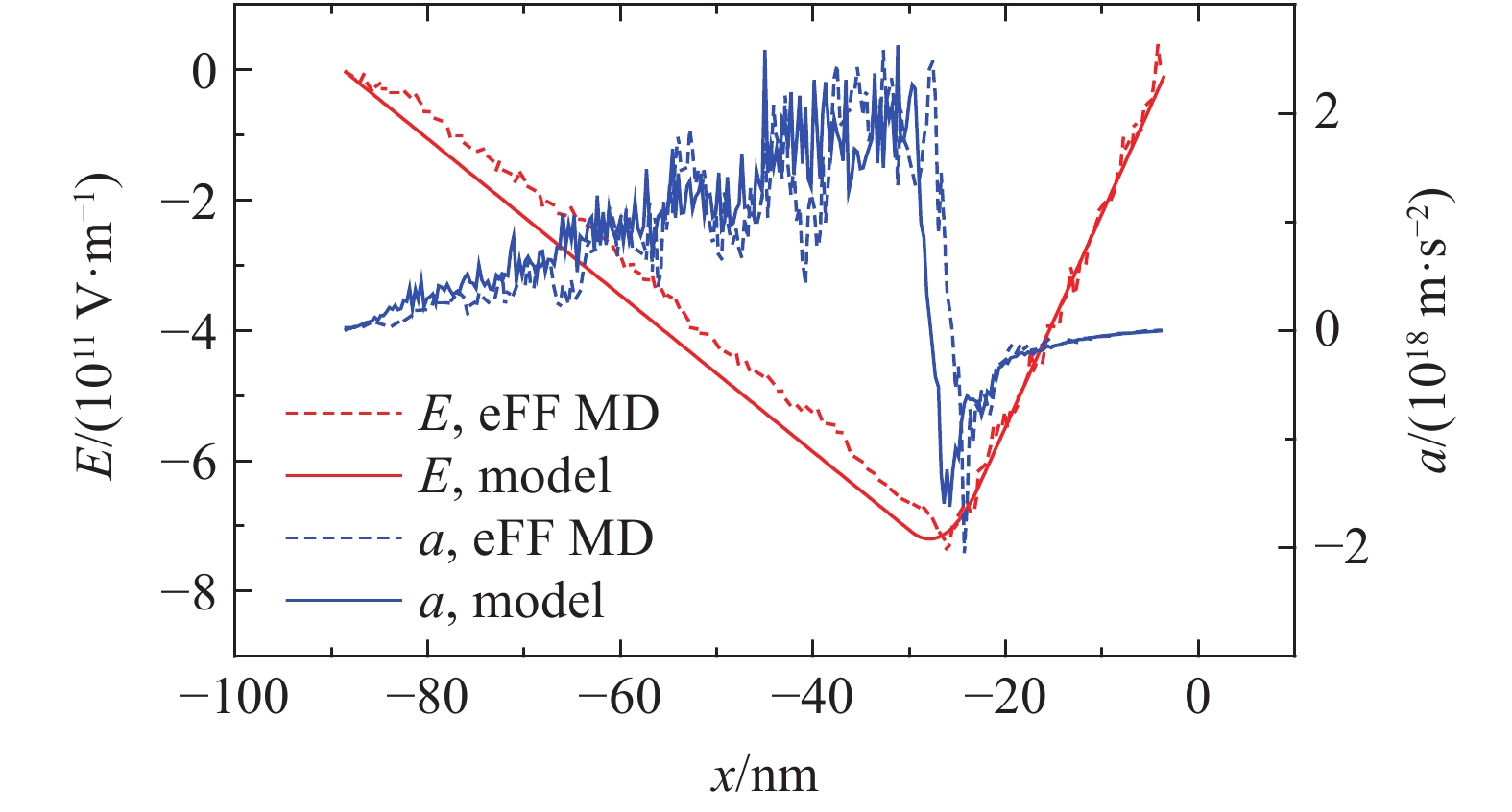
如前所述,在极端加载条件下,电荷分离会诱导附加电场的产生。本研究根据模拟结果构建了如图3(a)所示的一维电荷分布模型。为验证该模型的合理性,对模型进行电势积分获得一维分布的电场,如图4中红实线所示。
由于电荷分离,激波前后的物质不再呈中性状态,而是分别带部分负电和正电。在附加电场中必然产生加速度,其计算表达式如下
a=ρqEρm(15) (15) 式中:E为附加电场强度,ρq和ρm分别为单位体积下的物质带电量和物质密度,可通过分子动力学模拟结果的统计得到。
同时根据积分获得的一维分布的电场,计算各处带电物质获得的一维加速度分布,如图4中蓝色实线所示。图4还给出了根据eFF MD模拟结果一维统计获得的电场分布(红色虚线)和物质加速度分布(蓝色虚线),可见二者基本吻合。说明本研究建立的一维电荷分布模型基本合理。
2.3.2 金属/气体界面附近金属物质的加速度模型
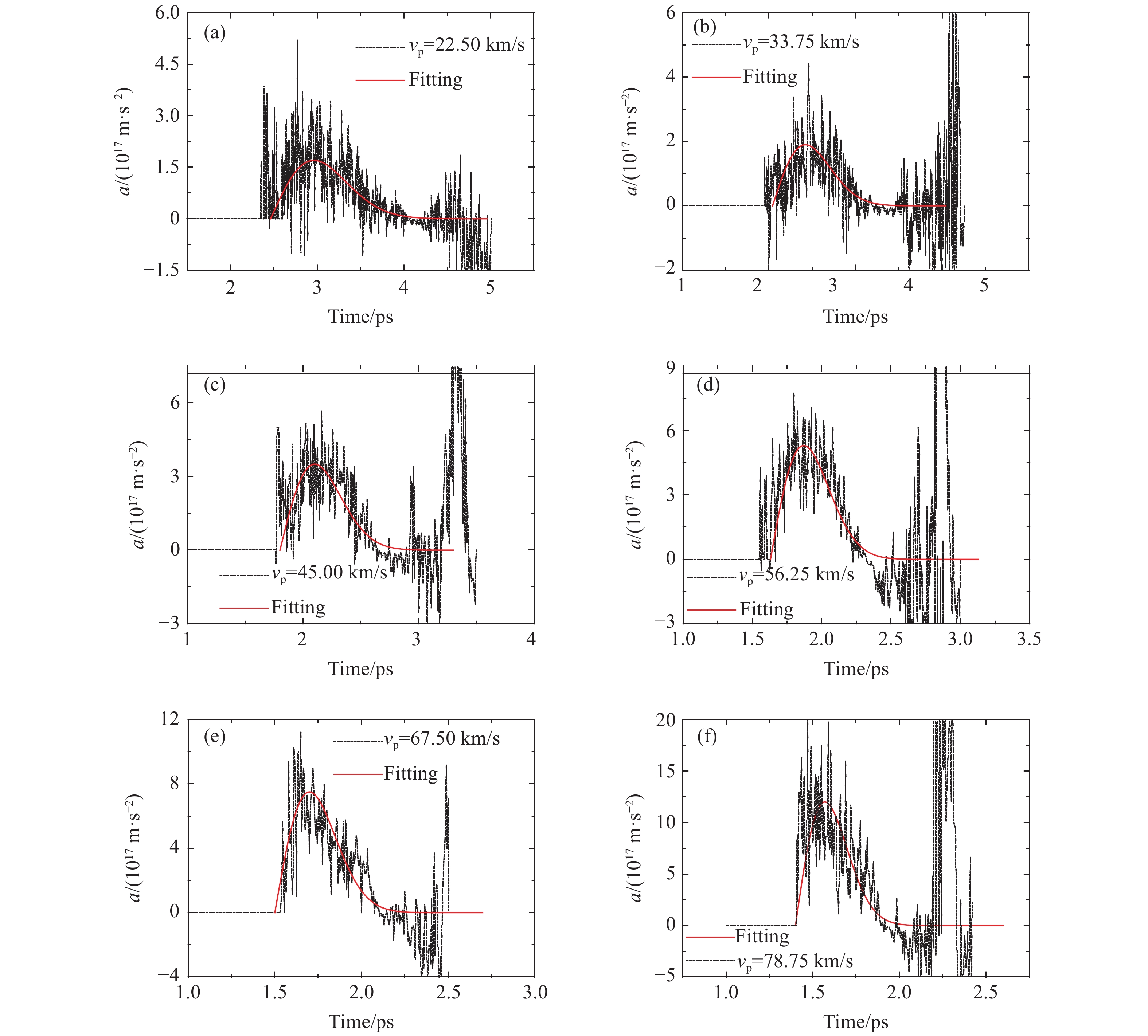
由于RM不稳定性的主要演化特征表现为界面物质扰动的振幅增长及物质混合,因此在极端条件下,激波诱导电荷分离导致附加电场的产生,进而引起界面物质的附加加速效应,可能显著影响界面演化。为深入理解极端条件下RM不稳定性的演化特征,特别是附加电场对界面物质的加速效应,对金属/气体界面附近金属侧物质(Li和H2物质的量之比0.6~0.9,厚度在0~2.0 nm区间)的加速度进行跟踪统计(以激波到达界面位置为统计起点),获得了不同冲击加载速度vp下界面附近金属物质的附加加速度随时间变化曲线,如图5所示。图5中虚线为根据eFF MD模拟结果统计分析获得,由于电子和离子的动态运动效应,统计值有一定涨幅落差,因此虚线呈现一定的振荡特征。对结果采用Rayleigh模型((16)式)进行拟合,如图5中红实线所示。综合来看,可以获得以下几点认识。
(1)界面附近金属物质获得的加速度呈脉冲形式。当激波刚到达界面位置时,电荷分离区跨越气/固界面,界面附近金属侧物质处于分离区中心区域,净电荷接近零;尽管此时分离区电场强度较高,但目标区受到的电场力较弱,加速度较低。随着激波往前推进,电荷分离区亦往前推进,分离区的电荷扩散处于动态平衡,目标区的净电荷逐渐偏正,并迅速向峰值增加;此时目标区受到的电场力开始增强,加速度迅速向峰值挺近,形成脉冲尖峰。随后,由于激波速度大于界面运动速度,随着激波继续向前推进,电荷分离区逐渐远离界面;此时目标区还带有较强的正电荷,但该区电场强度迅速衰减,对应的加速度也迅速衰减,形成完整的加速脉冲效应。
(2)随着冲击加载速度的增加(从22.50 km/s增加至78.75 km/s),目标区域的峰值加速度迅速提高(从1.7×1017 m/s2增加至1.2×1018 m/s2),同时脉冲持续时间逐渐减小(从1.5 ps降至1.0 ps)。这是因为随着冲击加载速度的提高,压缩程度增强,电离强度增加,电荷分离区强度相应提高,导致峰值加速度提升;但同时激波运动速度加快,激波跨越界面的时间相应缩短,脉冲持续时间自然有所降低。
(3)需要指出的是,曲线后期呈现较大幅度的振荡,这是因为激波到达左侧边界发生了Re-shock现象,Re-shock导致电荷分离呈现较大幅度的振荡。不过这一过程不是本研究关注内容,在此不作讨论。
本研究拟合所采用的模型公式为
a(t)=amaxe1/2tτriseexp(−t22τrise) (16) 式中:amax和τrise分别代表加速度峰值和上升时间,拟合参数如表2所示,拟合曲线如图6所示。
表 2 不同加载速度下Rayleigh模型的拟合参数Table 2. The fitted parameters of Rayleigh model at different vpvp/(km·s–1) amax/(1017 m·s–2) τrise/ps 22.50 1.7 0.50 33.75 1.9 0.38 45.00 3.5 0.30 56.25 5.3 0.24 67.50 7.5 0.20 78.75 12.0 0.17 从图6中可以明显看出amax和τrise分别随初始加载速度呈指数上升和指数下降趋势。这反映了拟合模型的合理性,即峰值加速度及脉冲上升时间与冲击强度的非线性关系。进一步对两个参数进行拟合,得到如下表达式
amax=6.23320×10¹⁶×e0.03744vp(17) (17) τrise=0.77369×e−0.02035vp(18) (18) 将(17)式和(18)式代入(16)式,可以获得界面附近金属侧物质受到激波压缩电离诱导形成附加电场的加速度经验公式
a(t,vp)=6.23320×10¹⁶×e0.03744vp+0.5×t0.77369×e−0.02035vp×exp(−t21.54738×e−0.02035vp) (19) 这是在本计算模型条件下冲击加载速度在20~80 km/s范围内激波压缩电离诱导附加电场引起的界面金属侧物质附加加速度的经验模型,揭示了极端加载条件下物质电离引起的附加电场对界面物质运动影响的基本特征。从积分效应来看,虽然其脉冲时间在皮秒量级,但所导致的界面物质的附加速度增量可达百千米每秒量级,显然不可忽视。当然,这只是界面物质加速的一方面,其他作用力耦合后,最终效应取决于综合效果。
3. 结 论
采用基于电子力场势函数的分子动力学方法,模拟了极端加载条件下金属/气体(Li/H2)平滑界面运动过程,对激波压缩电离过程及电荷扩散在激波附近诱导的电荷分离效应进行了理论分析和结果统计,发现了电荷分离诱导附加电场及其对界面物质加速作用的现象,进一步开展了理论建模和经验拟合分析,获得了电离引起界面附近金属侧物质附加加速度的经验模型,主要获得如下结论:
(1)极端冲击加载下,激波诱导附加电场的基本机理是,极端冲击使材料电离出较轻的电子和较重的离子,电子和离子的扩散差异导致在激波附近形成电荷分离区并达到动态扩散平衡,诱导出附加电场;
(2)统计分析发现,电荷分离区的宽度和强度在激波运动过程中基本保持稳定,它们仅与初始冲击加载速度相关,即与激波强度相关,呈非线性关系;
(3)由附加电场引起的界面物质的附加加速效应可能显著影响界面演化,统计分析发现,界面处金属侧的加速度满足Rayleigh模型,呈脉冲形态,揭示了极端加载条件下物质电离引起的附加电场对界面物质运动影响的基本特征,从积分效应来看,虽然其脉冲时间在皮秒量级,但其影响却不可忽视。
需要指出的是,本研究结果基于微观分子动力学模拟,其尺度在百纳米量级,相关结论尽管揭示了内在机理,但在一定程度上还受尺度效应的限制。后续工作将进一步加大模拟尺度并开展理论建模,进而推广到宏观尺度范围,使之更贴合工程实际工况。
-
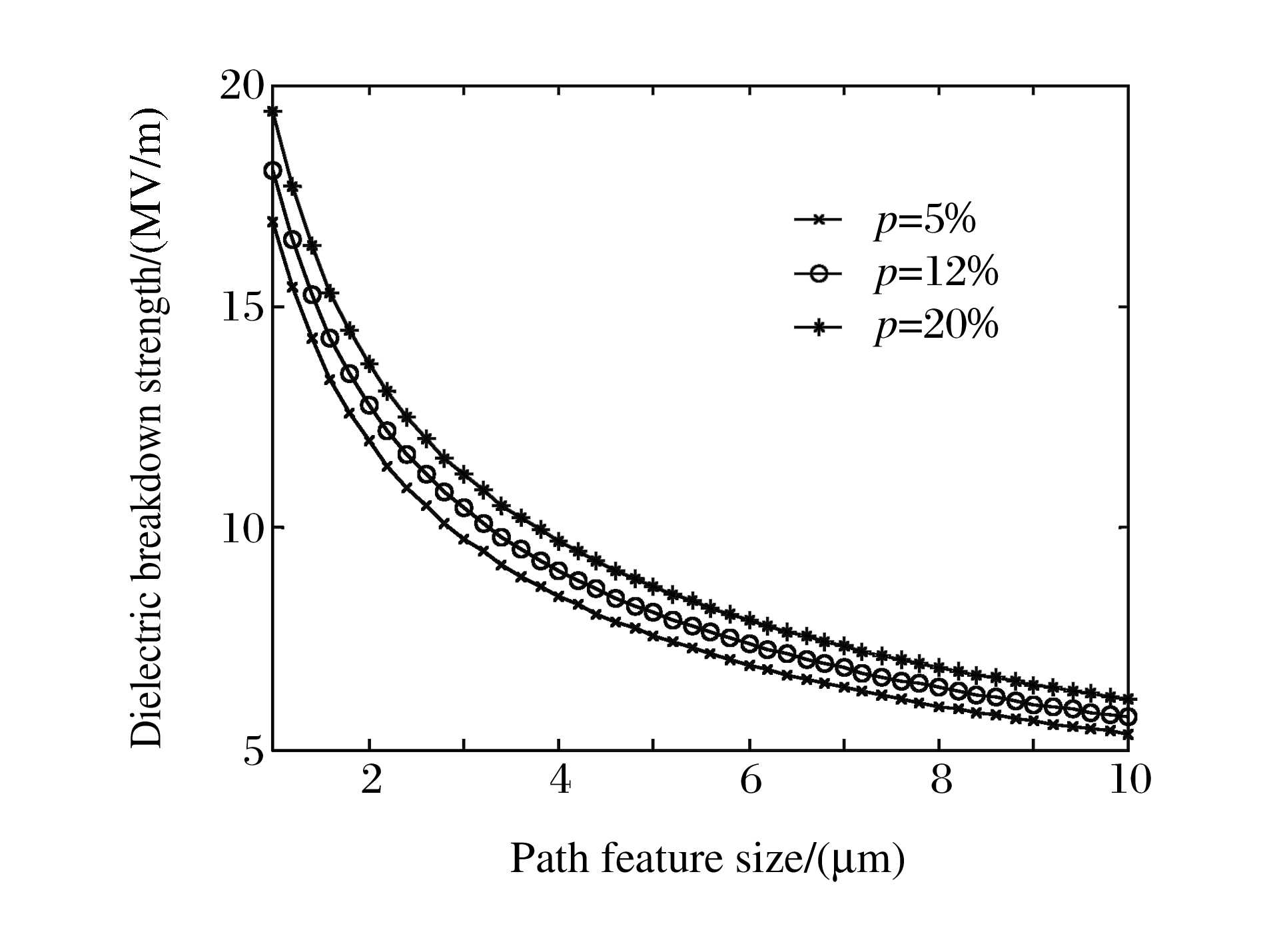
表 1 不同孔隙率及不同造孔剂的PZT95/5铁电陶瓷材料的击穿临界电场强度
Table 1. Dielectric breakdown strength of PZT95/5 ceramics with different porosities and pore formers
Material[17] Porosity/
(%)Relative dielectric
constantYoung's
modulus/(GPa)Path
size/(μm)Predicted breakdown
strength/(kV/m)Experimental breakdown
strength/(kV/m)Dense material
by hot-press
method0.4 314 148 1.00 16 500 15 000 Dense 4.1 309 148 5.00 7 460 6 800 PMMA
(Spherical shape)7.2 281 136 6.00 7 140 - 11.2 252 121 7.00 6 980 - 13.5 241 112 8.00 6 680 6 600 Dextrin
(Irregular pores)8.9 249 121 7.50 6 790 6 650 10.7 236 112 8.00 6 750 6 550 -
[1] Setchell R E. Shock wave compression of the ferroelectric ceramic Pb0.99(Zr0.95Ti0.05)0.98Nb0.02O3: Microstructural effects[J]. J Appl Phys, 2007, 101(5): 053525. doi: 10.1063/1.2697428 [2] 刘高旻, 张毅, 杜金梅, 等. PZT95/5-2Nb铁电陶瓷脉冲换能电输出[J].功能材料与器件学报, 2007, 13(4): 371-374. http://www.cnki.com.cn/Article/CJFDTotal-GNCQ200704012.htmLiu G M, Zhang Y, Du J M, et al. Electrical output of PZT95/5-2Nb pulsed power supply[J]. Journal of Functional Materials and Devices, 2007, 13(4): 371-374. (in Chinese) http://www.cnki.com.cn/Article/CJFDTotal-GNCQ200704012.htm [3] 陈学峰, 刘雨生, 冯宁博, 等.冲击压力和温度老化对PZT95/5铁电陶瓷放电的影响[J].电子元件与材料, 2009, 28(7): 1-4. http://d.wanfangdata.com.cn/Periodical/dzyjycl200907001Chen X F, Liu Y S, Feng N B, et al. Effects of shock pressure and temperature aging on the discharge behavior of PZT95/5 ferroelectric ceramics[J]. Electronic Components and Materials, 2009, 28(7): 1-4. (in Chinese) http://d.wanfangdata.com.cn/Periodical/dzyjycl200907001 [4] Storz L J, Dungan R H. A study of the electrical, mechanical, and microstructural properties of 95/5 PZT as a function of pore former type and concentration, SAND 85-1612[R]. USA: Sandia National Laboratories, 1986. [5] Tuttle B A, Yang P, Gieske J H, et al. Pressure-induced phase transformation of controlled-porosity Pb(Zr0.95Ti0.05)O3 ceramics[J]. J Am Ceram Soc, 2001, 84(6): 1260-1264. doi: 10.1111/j.1151-2916.2001.tb00826.x/full [6] Yang H, Dong X L, Zhong N, et al. Dielectric breakdown properties of Zr-rich lead zirconate titanate ceramics[J]. Jpn J Appl Phys, 2004, 43(11A): 7579-7582. doi: 10.1143/JJAP.43.7579 [7] 曾涛, 董显林, 毛朝梁, 等.孔隙率及晶粒尺寸对多孔PZT陶瓷介电和压电性能的影响及机理研究[J].物理学报, 2006, 55(6): 3073-3079. http://www.cnki.com.cn/Article/CJFDTotal-WLXB200606072.htmZeng T, Dong X L, Mao C L, et al. Effects of porosity and grain sizes on the dielectric and piezoelectric properties of porous PZT ceramics and their mechanism[J]. Acta Physica Sinica, 2006, 55(6): 3073-3079. (in Chinese) http://www.cnki.com.cn/Article/CJFDTotal-WLXB200606072.htm [8] Zeng T, Dong X L, Mao C L, et al. Effects of pore shape and porosity on the properties of porous PZT 95/5 ceramics[J]. J Eur Ceram Soc, 2007, 27(4): 2025-2029. doi: 10.1016/j.jeurceramsoc.2006.05.102 [9] Nie H C, Feng N B, Chen X F, et al. Enhanced ferroelectric properties of intragranular-porous Pb(Zr0.95Ti0.05)O3 ceramic fabricated with carbon nanotubes[J]. J Am Ceram Soc, 2010, 93(3): 642-645. doi: 10.1111/j.1551-2916.2009.03479.x [10] Setchell R E. Shock wave compression of the ferroelectric ceramic Pb0.99(Zr0.95Ti0.05)0.98Nb0.02O3: Depoling currents[J]. J Appl Phys, 2005, 97(1): 013507. doi: 10.1063/1.1828215 [11] Feng N B, Nie H C, Chen X F, et al. Depoling of porous Pb0.99(Zr0.95Ti0.05)0.98Nb0.02O3 ferroelectric ceramics under shock wave load[J]. Current Appl Phys, 2010, 10(6): 1387-1390. doi: 10.1016/j.cap.2010.04.012 [12] Sindeyev Y G, Yurkevich V E. Electrical breakdown in ferroelectric ceramics(a review)[J]. Ferroelelectrics, 1990, 110: 193-218. doi: 10.1080/00150199008008916 [13] Zhou Y X, Yoshimura N. Short-time DC breakdown phenomena in BaTiO3-based multilayer ceramic capacitors[J]. Jpn J Appl Phys, 1999, 38: 1412-1417. doi: 10.1143/JJAP.38.1412 [14] Shin B C, Kim S C, Nahm C W, et al. Nondestructive testing of ceramic capacitors by partial discharge method[J]. Mater Lett, 2001, 50(2): 82-86. http://www.sciencedirect.com/science/article/pii/S0167577X00004201 [15] 杨洪.高抗电强度PZT95/5型铁电陶瓷的研制及击穿机理的研究[D].上海: 上海硅酸盐研究所, 2006: 50-78.Yang H. Fabrication and breakdown mechanism research of PZT95/5 ceramics with high dielectric breakdown properties[D]. Shanghai: Shanghai institute of ceramics, 2006: 50-78. (in Chinese) [16] Geis S, Fricke J, Löbmann P. Electrical properties of PZT aerogels[J]. J Euro Ceram Soc, 2002, 22(7): 1155-1161. doi: 10.1016/S0955-2219(01)00426-5 [17] 曾涛.多孔PZT压电和铁电陶瓷的制备与性能研究[D].上海: 上海硅酸盐研究所, 2007: 65-83.Zeng T. Fabrication and properties of porous PZT based piezoelectric and ferroelectric ceramics[D]. Shanghai: Shanghai Institute of Ceramics, 2007: 65-83. (in Chinese) [18] Gerson R, Marshall T C. Dielectric breakdown of porous ceramics[J]. J Appl Phys, 1959, 30(11): 1650-1653. doi: 10.1063/1.1735030 [19] 冯宁博, 贺红亮, 董显林.高应变率加载下材料的损伤破碎规律[J].高能量密度物理, 2007, (4): 152-164. http://www.cqvip.com/QK/97600A/20074/26215254.htmlFeng N B, He H L, Dong X L. Damage and broken laws of materials in the high strain rate loading[J]. High Energy Density Physics, 2007, (4): 152-164. (in Chinese) http://www.cqvip.com/QK/97600A/20074/26215254.html [20] 张福平, 杜金梅, 刘雨生, 等. PZT95/5陶瓷电致失效机理研究[J].物理学报, 2011, 60(5): 057701. http://www.cqvip.com/QK/94684X/20115/37798769.htmlZhang F P, Du J M, Liu Y S, et al. Failure mechanism of PZT95/5 under direct current and pulsed electric field[J]. Acta Phys Sinica, 2011, 60(5): 057701. (in Chinese) http://www.cqvip.com/QK/94684X/20115/37798769.html [21] Coelho R, Aladenize B.电介质材料及其介电性能[M].张治文, 译.北京: 科学出版社, 2000: 162-192.Coelho R, Aladenize B. The Dielectric Material and Its Dielectric Properties[M]. Translated by Zhang Z W. Beijing: Science Press, 2000: 162-192. (in Chinese) [22] Crichton G C, Karlsson P W, Pedersen A. Partial discharges in ellipsoidal and spheroidal voids[J]. IEEE Trans Electr Insul, 1989, 24(2): 335-342. doi: 10.1109/14.90292 [23] Mcallister I W, Crichton G C. Influence of bulk dielectric polarization upon partial discharge transients effect of heterogeneous dielectric geometry[J]. IEEE T Dielect El In, 2000, 7(1): 124-132. doi: 10.1109/94.839350 [24] Pedersen A, Crichton G C, Mcallister I W. The theory and measurement of partial discharge transients[J]. IEEE Trans Electr Insul, 1991, 26(3): 487-497. doi: 10.1109/14.85121 [25] Stark K H, Garton C G. Electric strength of irradiated polythene[J]. Nature, 1955, 176(4495): 1225-1226. doi: 10.1038/1761225a0 [26] Fothergill J C. Filamentary electromechanical breakdown[J]. IEEE Trans Electr Insul, 1991, 26(6): 1124-1129. doi: 10.1109/14.108149 [27] Schneider G A. Influence of electric field and mechanical stresses on the fracture of ferroelectrics[J]. Annu Rev Mater Res, 2007, 37: 491-538. doi: 10.1146/annurev.matsci.37.052506.084213 [28] Banno H. Effects of shape and volume fraction of closed pores on dielectric elastic and electromechanical properties of dielectric and piezoelectric ceramics: A theoretical approach[J]. Am Ceram Soc Bull, 1987, 66(9): 1332-1337. http://www.researchgate.net/publication/279589309_Effects_of_Shape_and_Volume_Fraction_of_Closed_Pores_on_Dielectric_Elastic_and_Electromechanical_Properties_of_Dielectric_and_Piezoelectric_CeramicsA_Theoretical_Approach [29] Phani K K, Niyogi S K. Young's modulus of porous brittle solids[J]. J Mater Sci, 1987, 22: 257-263. doi: 10.1007/BF01160581 -


 下载:
下载:


 下载:
下载:


